
Golf Mk5
| Removing and installing rear axle |
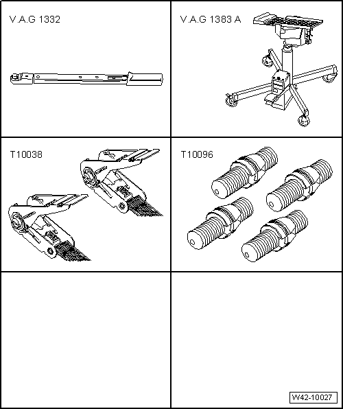
| Special tools and workshop equipment required |
| t | Torque wrench -V.A.G 1332- |
| t | Engine and gearbox jack -V.A.G 1383/A - |
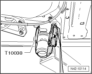
| t | Tensioning strap -T10038- |
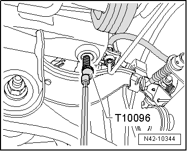
| t | Locating pins -T10096- |
|
|
|
|
|
|
|
|
|
|
|
|
|
|
|
|
|
|
|
 WARNING
|
|
 Note
Note
|
|
Note
Note
|
|
Note
|
|
| Specified torques |
| Component | Specified torque | ||
Subframe to body
| 90 Nm + 90° | ||
| Shock absorber to wheel bearing housing | 180 Nm | ||
Mounting bracket to body
| 50 Nm + 45° | ||
| Handbrake cable to trailing arm → Brake systems; Rep. gr.46 | |||