
Golf Mk5
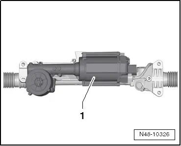
| Removing and installing steering box, right-hand drive vehicle (3rd generation) from model year 2009 |

| Special tools and workshop equipment required |
| t | Torque wrench -V.A.G 1331- |
| t | Torque wrench -V.A.G 1332- |
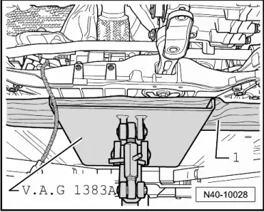
| t | Engine and gearbox jack -V.A.G 1383 A- |
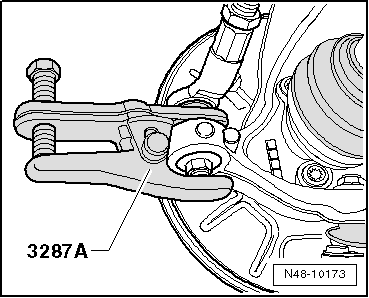
| t | Ball joint puller -3287 A- |
|
|
|
|
|
 Caution
|
|
|
|
|
|
|
|
|
|
|
|
|
|
|
|
|
|
|
|
|
|
|
|
|
|
 Note
Note
Note
|
|
| Specified torques |
| Component | Specified torque | ||||
Subframe to body
| 70 Nm + 90° | ||||
Anti-roll bar to subframe
| 20 Nm + 90° | ||||
Anti-roll bar to coupling rod
| 65 Nm | ||||
Swivel joint to cast steel suspension link
| 60 Nm | ||||
Swivel joint to sheet steel or forged aluminium suspension link
| 100 Nm | ||||
Shield to subframe
| 6 Nm | ||||
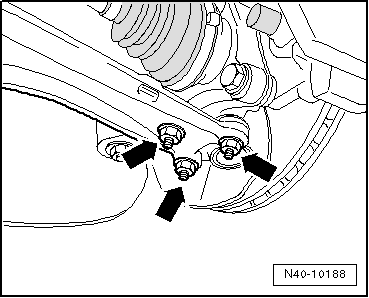
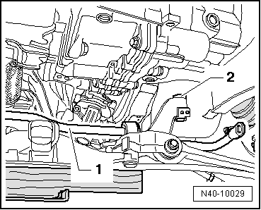
Steering box to subframe
| 50 Nm + 90° | ||||
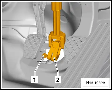
Universal joint to steering box
| 30 Nm | ||||
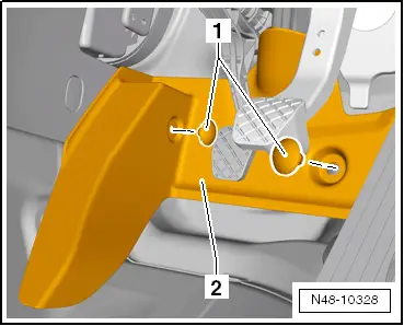
Shield to steering box
| 6 Nm | ||||
Track rod ball joint to wheel bearing housing
| 20 Nm + 90° | ||||
| Exhaust system bracket to subframe → Engine; Rep. gr.26 | |||||
| Specified torques for pendulum support to gearbox |
| Bolt | Specified torque | ||
M10 x 35
| 50 Nm + 90° further | ||
M10 x 75
| 50 Nm + 90° further |