| –
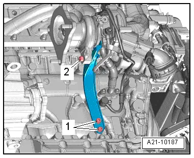
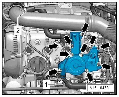
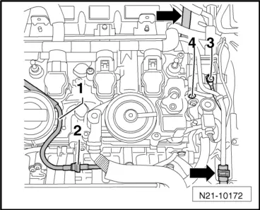
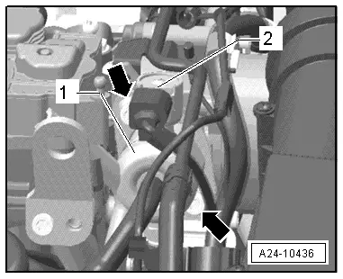
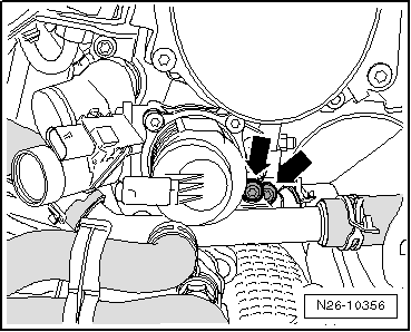
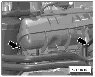
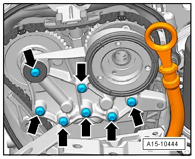
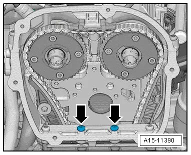
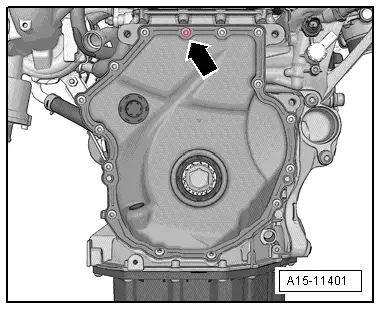
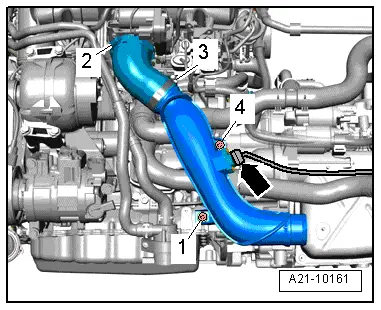
| Unscrew bolts -arrows-. |
| –
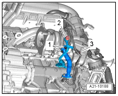
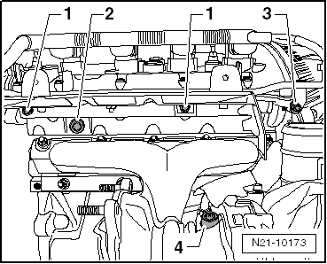
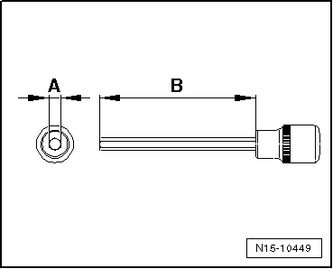
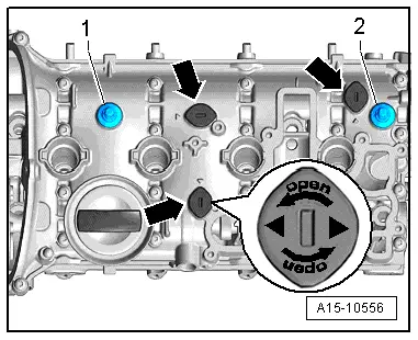
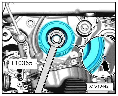
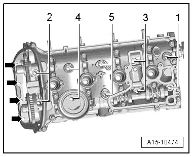
| Unscrew cylinder head bolts using polydrive bit and socket -T10070- in sequence -1 … 5-. |

Note | t
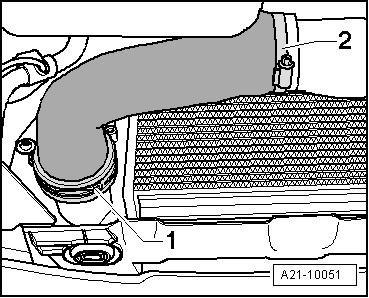
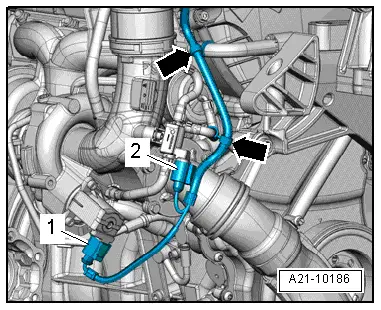
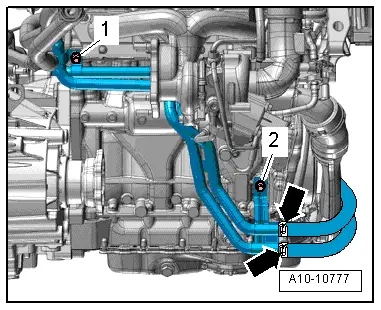
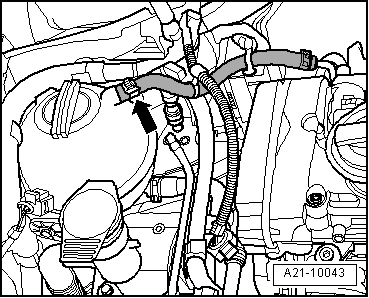
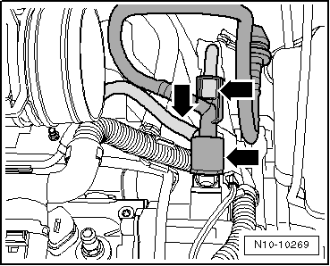
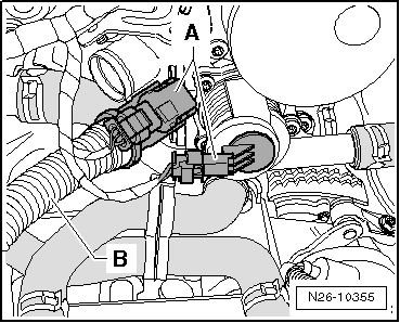
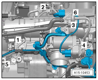
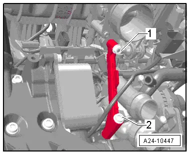
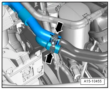
| Make sure all hoses/pipes and wiring on component are removed. |
| t
| Ensure tensioning rail and guide rail are not damaged when lifting off cylinder head. |
| –
| Place cylinder head onto soft surface (foam plastic). |

Caution | Avoid damage to sealing surfaces. |
| t
| Carefully remove sealant residue from cylinder head and cylinder block. |
| t
| Ensure that no long scores or scratches are made on the surfaces. |
| Avoid damage to cylinder block. |
| No oil or coolant must be allowed to remain in the blind holes for the cylinder head bolts in the cylinder block. |
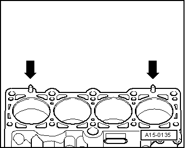
| Ensure that cylinder head gasket seals properly: |
| t
| Carefully remove remains of emery and abrasives. |
| t
| Do not remove new cylinder head gasket from packaging until it is ready to be fitted. |
| t
| Handle the cylinder head gasket very carefully to prevent damage to the silicone coating or the indented area of the gasket. |
| Avoid damage to open valves. |
| When installing an exchange cylinder head, the plastic protectors fitted to protect the open valves should not be removed until the cylinder head is ready to be fitted. |
| Avoid damage to valves and piston crowns after working on valve gear. |
| Turn the engine carefully at least 2 rotations to ensure that none of the valves make contact when the starter is operated. |
|
Note | t
| Renew bolts tightened with specified tightening angle. |
| t
| Renew self-locking nuts as well as gaskets, seals and O-rings. |
| t
| When installing a replacement cylinder head, the contact surfaces between hydraulic compensation elements, roller rocker fingers and cams must be oiled before installing the camshafts. |
| t
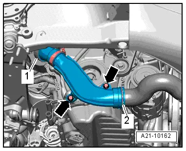
| Hose connections and air duct pipes must be free of oil and grease before assembly. |
| t
| In order to be in a position to securely attach the charge air hoses on their connections, the worm screws of the used hose clips have to the sprayed with penetrating spray before installing. |
| t
| When cylinder head or cylinder head gasket is renewed, the entire coolant and the engine oil must be changed. |
| Procedure for new cylinder head |
|
|
|

 WARNING