
New Beetle
| I - Repairing front drive shaft with constant velocity joint |
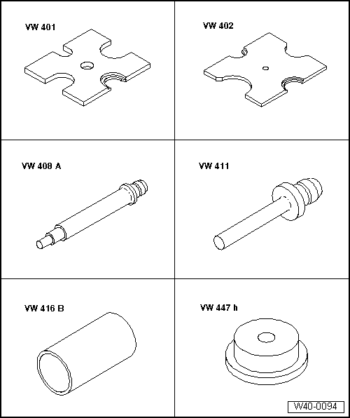
| Special tools and workshop equipment required |
| t | Thrust plate -VW 401- |
| t | Thrust plate -VW 402- |
| t | Press tool -VW 408 A- |
| t | Press tool -VW 411- |
| t | Tube -VW 416 B- |
| t | Thrust washer -VW 447 H- |
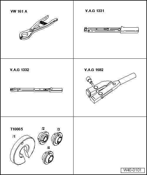
| t | Circlip pliers -VW 161 A- |
| t | Torque wrench -V.A.G 1331- |
| t | Torque wrench -V.A.G 1332- |
| t | Pliers -V.A.G 1682- |
| t | Assembly tool -T10065- |
|
| Grease | of which in: | ||
| Outer joint | Total quantity | Joint | Boot |
| Ø mm | [g] | [g] | [g] |
| 81 | 80 | 40 | 40 |
| 90 | 120 | 80 | 40 |
| Inner joint | |||
| Ø mm | |||
| 94 | 90 | 40 | 50 |
| 100 | 120 | 50 | 70 |
|
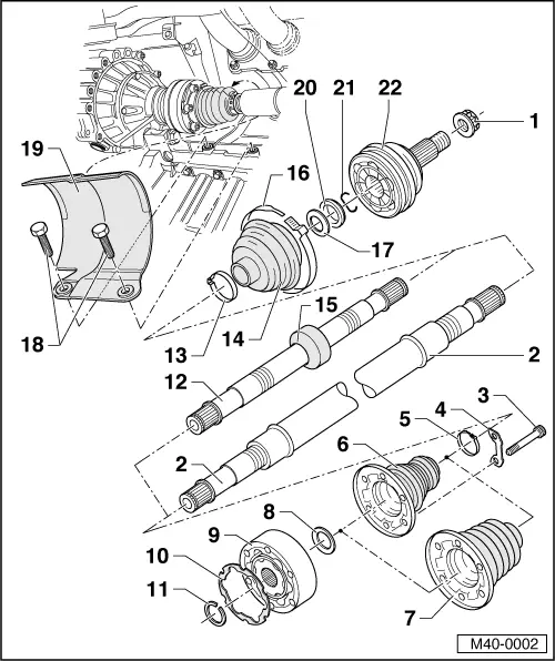
| 1 - | 12-point nut (self-locking) |
| q | Tightening → Chapter. |
| q | Remove any paint residue or corrosion on thread of outer joint before fitting nut. |
| 2 - | Right drive shaft (tubular shaft) |
| 3 - | Multi-point socket head bolt |
| q | Specified torques → Anchor |
| 4 - | Locking plate |
| 5 - | Clamp |
| q | Renew. |
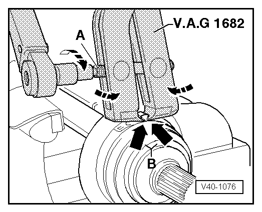
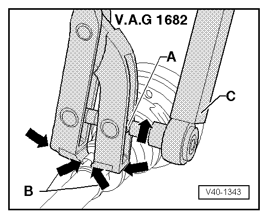
| q | Tightening → Fig. |
| 6 - | Boot for inner constant velocity joint |
| q | Material: → Hytrel (polyester elastomer) |
| q | Without breather hole |
| q | Check for splits and chafing |
| q | Drive off constant velocity joint with a drift |
| q | Coat sealing surface of constant velocity joint with -D 454 300 A2- before installing. |
| 7 - | Boot for inner constant velocity joint |
| q | Material: Rubber |
| q | With vent hole. |
| q | Check for splits and chafing |
| q | Drive off constant velocity joint with a drift |
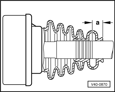
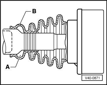
| q | Installation position for left shaft → Fig.. |
| q | Installation position for right shaft → Fig.. |
| q | Coat sealing surface of constant velocity joint with -D 454 300 A2- before installing. |
| 8 - | Dished spring |
| q | Installation position → Fig. |
| 9 - | Inner constant velocity joint |
| q | Renew only as complete unit |
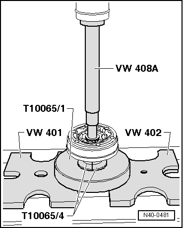
| q | Pressing off → Fig. |
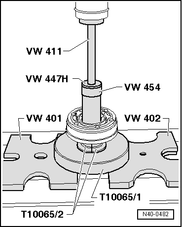
| q | Pressing on → Fig. |
| q | Greasing → . |
| q | Checking → Chapter |
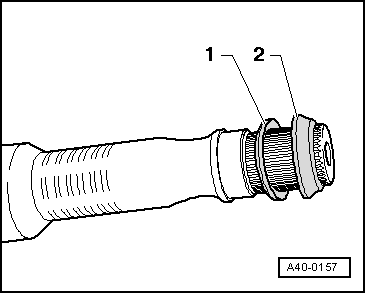
| 10 - | Seal |
| q | Adhesive surface on constant velocity joint must be free of oil and grease! |
| q | Renew. |
| q | Pull off protective foil and stick into joint. |
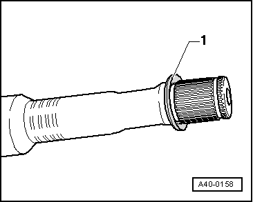
| 11 - | Retaining ring |
| q | Remove and install using -VW 161 A- |
| 12 - | Left drive shaft (solid shaft) |
| q | Renew. |
| q | Tightening → Fig. |
| 13 - | Clamp |
| 14 - | Boot |
| q | Check for splits and chafing |
| q | Material: Hytrel (polyester elastomer) |
| 15 - | Balance weight |
| 16 - | Clamp |
| q | Renew. |
| q | Use clamp tensioner -V.A.G 1682- to tighten → Fig. |
| 17 - | Dished spring |
| q | Installation position → Fig. |
| 18 - | Hexagon bolt |
| q | M10 x 28 |
| q | Specified torques → Anchor |
| 19 - | Protective cap |
| 20 - | Thrust washer |
| q | Installation position → Fig. |
| 21 - | Retaining ring |
| q | Renew. |
| q | Insert in groove in shaft |
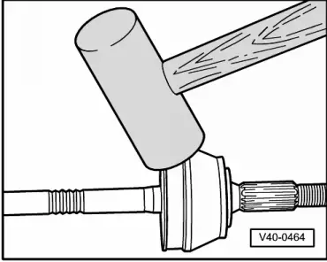
| 22 - | Outer constant velocity joint |
| q | Renew only as complete unit |
| q | Removing → Fig. |
| q | Installing: drive onto shaft to stop using a plastic mallet |
| q | Greasing → . |
| q | Checking → Chapter |
|
|
 Note
Note
|
|
|
|
|
|
Note
|
|
|
|
Note
|
|
|
|