
Passat Wagon V6-2792cc 2.8L DOHC (1994)
Engine Control Module: Description and Operation
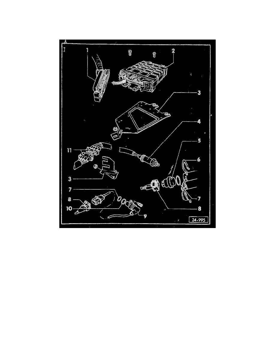
ECM Component Layout
Motronic Engine Control Module (ECM), Component Layout
1 -
Motronic Engine Control Module (ECM) harness connector
-
before removing; ignition must have been switched oft for a minimum of 20 seconds
-
68 pin
2 -
Motronic Engine Control
Module (ECM) (J 220)
-
installation location: driver side of plenum panel in engine compartment
-
with DTC Memory.
-
Idle speed and ignition timing point.
3 -
Engine Control Module (ECM) mounting plate
4 -
Oxygen sensor (O2S) (G 39)
-
50 Nm (37 ft lb)
-
installation location: front exhaust pipe
-
coat threads with G5 but do not allow G5 to enter slotted area of sensor tip.
To check heater voltage supply:
-
switch Fluke 83 multimeter to 20 Volt range connect multimeter between terminals 1 (red/white) and 2 (brown)
-
start engine and let idle
-
must be approx. battery voltage