
Passat Wagon V6-2792cc 2.8L DOHC (1994)
Ignition Coil Pack: Testing and Inspection
CHECKING IGNITION COIL
^
"Ignition Output 1," "Ignition Output 2" or "Ignition Output 3" displayed by VAG 1551 On Board Diagnostic (OBD) program (function 02,
Check DTC Memory).
^
Camshaft Position (CMP) Sensor OK.
^
Carry out electrical testing, test steps 2 and 24.
^
Check voltage supply to Ignition Coil (N152) only if the engine will not start.
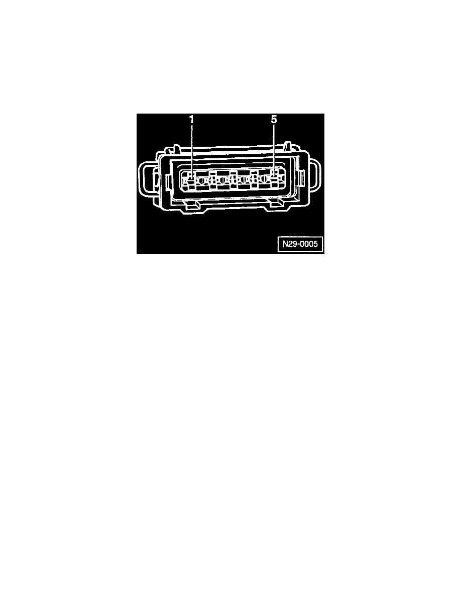
CHECKING VOLTAGE SUPPLY
-
Disconnect 5-pin connector from Ignition Coil.
-
Connect Fluke 83 hand multimeter (US 1119 or equivalent) to measure voltage across connector terminals -1- and -5-, using cables from VAG
1594 adapter kit.
-
Switch ignition ON.
-
Multi meter should read 10 Volts (minimum).
-
Switch ignition OFF.
CHECKING ACTIVATION
-
Remove fuse 18 (S18).
-
Connect VAG 1527B voltage tester (LED test light) to connector terminals -5- and -2-, using cables from VAG 1594 adapter kit.
-
Operate starter and check ignition signal from Motronic Engine Control Module (ECM) (J220).
NOTE: LED must flicker.
-
Repeat the test twice more, with the voltage tester connected to terminals -5- and -3-, then -5- and -4-.
-
If LED does NOT flicker, replace Motronic Engine Control Module.