
Polo Mk3
|
Removing and installing cylinder head
Removing, installing and tensioning toothed belt
|
 |
|
Removing Note: Adjustment work on toothed belts must be performed on cold engines only.
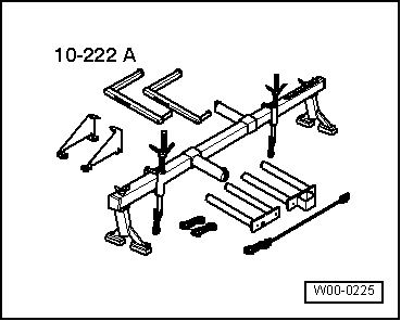
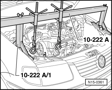
=> General body repairs exterior; Repair group 50; Body front; Assembly overview
|
 |
|
|
 |
|
|
 |
|
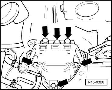
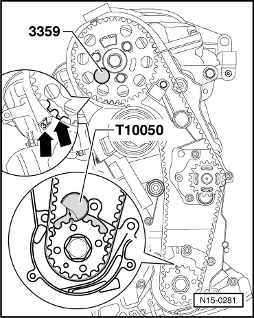
Note: → Turn the crankshaft until the mark on the crankshaft pulley is facing up and the arrow on the rear section of the toothed belt guard aligns with lug on the hub sender wheel -arrows-.
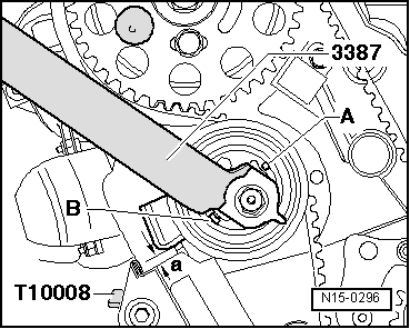
Note: The marks on the crankshaft sprocket and the crankshaft stop must align. At the same time, the shaft of the crankshaft stop must engage in the drilling in the sealing flange.
|
 |
|
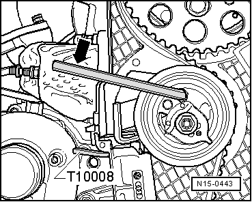
Note: If the hexagon key is not inserted deeply enough there is a great danger that key will slip and round-off the hexagon drive.
|
 |
|
Installing |
 |
|
|
Note: Adjustment work on toothed belts must be performed on cold engines only.
|
 |
|
|
|
|
Notes:
|
 |
|
Notes:
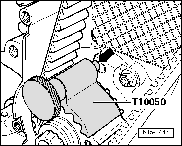
If dimension -a- is not achieved:
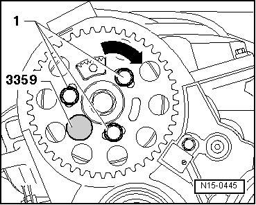
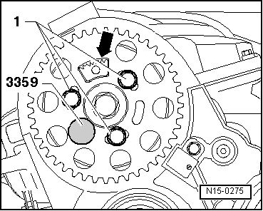
If the hub cannot be locked: |
|
|
|
 |
|
Notes:
=> General body repairs exterior; Repair group 50; Body front; Assembly overview
|