volkswagen Workshop Repair Guides

Volkswagen Workshop Service and Repair Manuals

Exhaust system > < Removing and installing pressure unit for charge pressure regulating valve
3-cyl. diesel engine, Mechanics
Checking charge pressure control
 
W21-0005

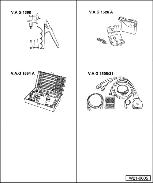
Special tools, workshop equipment, test and measuring appliances and auxiliary items required

  • ◆ V.A.G 1390 Vacuum pump
  • ◆ V.A.G 1526 Hand multimeter
  • ◆ V.A.G 1594 A Adapter set
  • ◆ V.A.G 1598/31 Test box
  • ◆ Fault reader V.A.G 1551 or vehicle system tester V.A.G 1552 with cable V.A.G 1551/3
  • ◆ Current flow diagram

Check conditions

  • ● No fault stored in fault memory

=> Repair group 01; Self-diagnosis; Interrogating and erasing fault memory

  • ● No leaks on intake and exhaust systems.
  • ● Control pipe to charge pressure regulating valve is not blocked, loose or leaking.
  • ● No faults in engine and fuel injection system
  • ● Engine oil temperature min. 80 °C

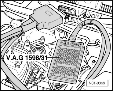
Test sequence

Observe following if test and measuring instruments are required during a test drive:

  • ◆ Test and measuring instruments must be secured to rear seat and operated by a 2nd person from this location.
  • If test and measuring instruments are operated from front passenger's seat and the vehicle is involved in an accident, there is a possibility that the person sitting in this seat may receive serious injuries when the airbag is triggered.
  • ‒ The charge pressure is measured with the fault reader V.A.G 1551 during a test drive.
 
N21-0136

To enable the charge pressure control to be checked it is essential that the charge pressure is first determined with charge pressure control deactivated.

  • ‒ → Pull off charge pressure control solenoid valve (N75) -1- connectors -2-.
  • ‒ With engine running at idle speed, connect fault reader V.A.G 1551 (V.A.G 1552) and select engine electronics control unit with the "Address word" 01:

=> Repair group 01; Self-diagnosis; Connecting fault reader V.A.G 1551 and selecting engine electronics control unit

 
→ Indicated on display:
Rapid data transfer    HELP
Select function XXX
  • ‒ Press keys 0 and 8 for the function "Read measured value block" and confirm entry with Q key.
 
→ Indicated on display:
Read measured value block    HELP
Input display group number XXX
  • ‒ Press keys 0, 1 and 1 for display group 11 and confirm entry by pressing Q.
 
→ Indicated on display:
Read measured value block 11    "
840 rpm    938 mbar    978 mbar    92 %
  • ‒ Accelerate vehicle in 3rd gear from about 1500 rpm using full throttle.
  • ‒ Press PRINT key on V.A.G 1551 at approx. 3000 rpm.
  •  
    → Specification in display zone 3: 1550...1750 mbar
    Read measured value block 11    ⇒
    3090 rpm    1866 mbar    1550 mbar    62 %

    If the charge pressure is not attained:

    • ‒ Check charge pressure control valve pressure unit and renew if necessary.
    • ‒ Check vacuum hoses .
    • ‒ Repeat charge pressure check.

    If the charge pressure has still not been attained:

    • ‒ Replace turbocharger.

    If the charge pressure is exceeded:

    • ‒ Test charge pressure control solenoid valve (N75). (Through-flow in hose from turbocharger via valve to pressure unit when connector is pulled off).
    • ‒ Check vacuum hoses => Page 21-11.
    • ‒ Check charge pressure control valve pressure unit as well as the operating rod and renew if necessary.
    • ‒ Check shaft mounting for charge pressure regulating valve in turbocharger for ease of movement.
      When corroded together, renew turbocharger.
    • ‒ If the measured charge pressure is OK., repeat charge pressure measurement with charge pressure control active:
    • ‒ Connector connected to solenoid valve charge pressure control -N75.

    Note:

    Separating connector on solenoid valve for charge pressure control -N75- causes a fault to be recorded. Interrogate and erase fault memory.

    • ‒ Interrogate fault memory:

    => Repair group 01; Self-diagnosis; Interrogating and erasing fault memory

    • ‒ With engine running at idle speed, connect fault reader V.A.G 1551 (V.A.G 1552) and select engine electronics control unit with the "Address word" 01:

    => Repair group 01; Self-diagnosis; Connecting fault reader V.A.G 1551 and selecting engine electronics control unit

     
    → Indicated on display:
    Rapid data transfer    HELP
    Select function XXX
    • ‒ Press keys 0 and 8 for the function "Read measured value block" and confirm entry with Q key.
     
    → Indicated on display:
    Read measured value block    HELP
    Input display group number XXX
    • ‒ Press keys 0, 1 and 1 for display group 11 and confirm entry by pressing Q.
     
    → Indicated on display:
    Read measured value block 11    "
    840 rpm    938 mbar    978 mbar    92 %
  • ‒ Accelerate vehicle in 3rd gear from about 1500 rpm using full throttle.
  • ‒ Press PRINT key on V.A.G 1551 at approx. 3000 rpm.
  •  
    → Specification on V.A.G 1551: 1800...2200 mbar (in display zone 3)
    Read measured value block 11    ⇒
    3090 rpm    1866 mbar    1917 mbar    62 %

    If the specification is not obtained:

    • ‒ Check solenoid valve for charge pressure control (N75) => Page 21-22
    • ‒ Check vacuum hoses => Page 21-11.

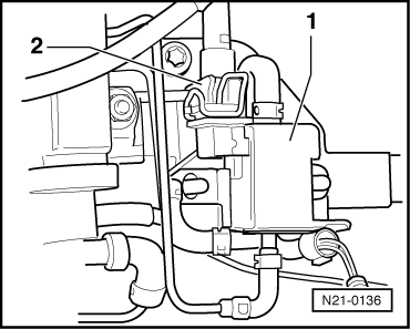
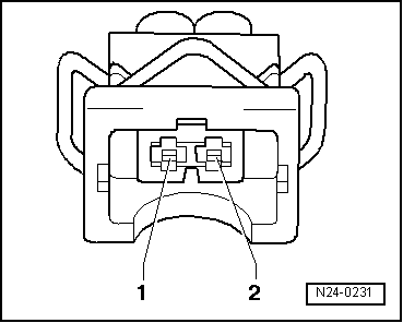
    Checking solenoid valve for charge pressure control (N75)

     
    N21-0136
    • ‒ Switch off ignition.
    • ‒ → Pull off charge pressure control solenoid valve (N75) -1- connectors -2-.
    • ‒ Measure resistance between valve contacts.

    Specification: 25...45ω

    If the specification is not obtained:

    • ‒ Replace charge pressure control solenoid valve (N75).
     
    N24-0231

    If the specification is obtained:

    • ‒ Switch on ignition.
    • ‒ → Measure valve's supply voltage at connector contact 1 and at engine earth.
          Specification: approx. battery voltage

    If the specification is not obtained:

    • ‒ Switch off ignition.
     
    N01-0369
    • ‒ → Connect test box V.A.G 1598/31 to control unit wiring harness. The engine control unit remains disconnected.
    • ‒ Check wiring between test box and connector for open circuit using current flow diagram.
          Contact 1 + socket 1 and 2
          Contact 2 + socket 62
          Wire resistance: max. 1.5 ω
    • ‒ Additionally check wires for short to one another, to vehicle earth and to battery positive.
          Specification: ∞ω

    If no fault is detected in the wiring:

    • ‒ Renew Diesel direct injection system control unit (J248)

    => Repair group 23; Renewing engine control unit, coding and matching; Renewing engine control unit

    Exhaust system > < Removing and installing pressure unit for charge pressure regulating valve