
Polo Mk3
|
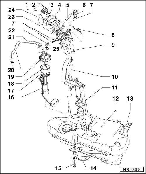
Removing and installing parts of fuel supply system
Removing and installing fuel tank with its attachments
|
 |
|
=> General body repairs, Exterior; Repair group 55; Tank flap unit |
|
|
|
|
|
|
|
|
|
|
|
|
 |
|
|
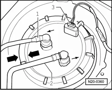
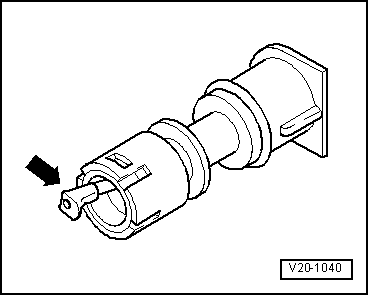
→ Fig. 2 Checking vent valve Lever in rest position: Closed Lever pushed in direction of arrow: Open Note: Before installing vent valve remove fuel tank cap. |