
Polo Mk3
|
Dismantling and assembling output shaft
Dismantling and assembling output shaft
|
 |
|
|
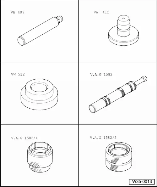
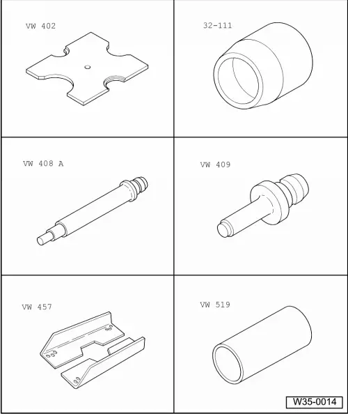
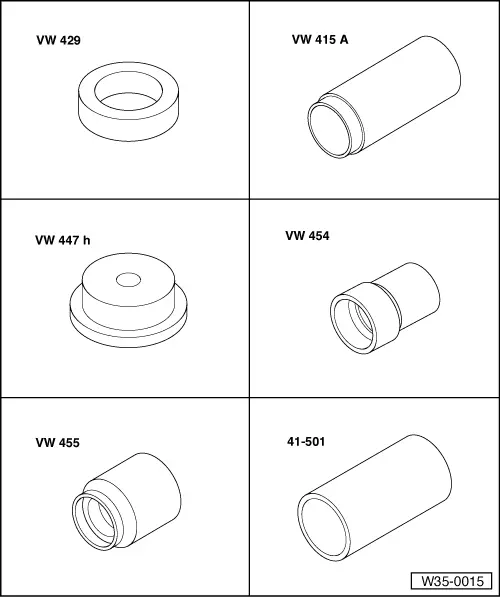
Special tools and workshop equipment required
|
 |
|
|
Special tools and workshop equipment required
|
 |
|
|
Special tools and workshop equipment required
|
 |
|
|
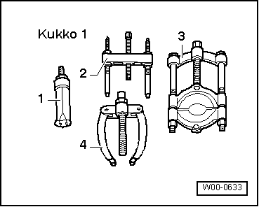
Special tools and workshop equipment required
|
 |
|
With 250 mm long hooks |
 |
|
|
Notes:
|
|
|
|
|
|
|
|
|
|
|
|
|
|
|
|
|
|
|
 |
|
|
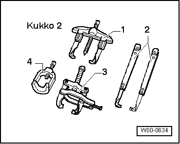
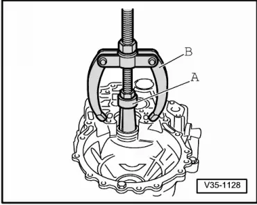
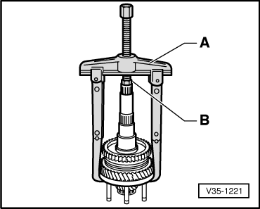
→ Fig.1 Pulling out small taper roller bearing outer race A - Internal extractor 37 ... 46 mm, e.g. Kukko 21/6 B - Counter support, e.g. Kukko 22/2 |
 |
|
|
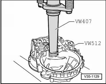
→ Fig.2 Pressing in small taper roller bearing outer race |
 |
|
|
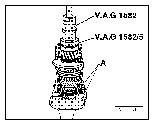
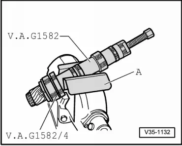
→ Fig.3 Pulling off small taper roller bearing inner race A - Vice clamps/vice
|
 |
|
|
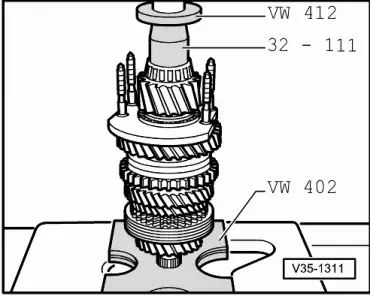
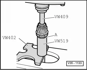
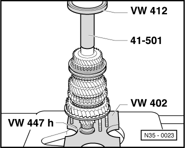
→ Fig.4 Pressing on small taper roller bearing inner race |
 |
|
|
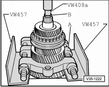
→ Fig.7 Pulling off large taper roller bearing inner race A - protective jaws
|
 |
|
|
→ Fig.8 Pressing on large taper roller bearing inner race A - Thrust washer
|
 |
|
|
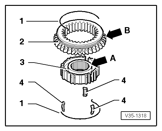
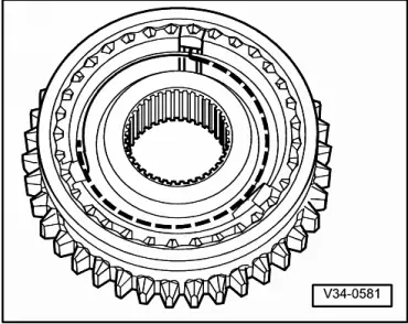
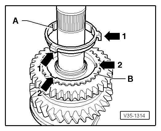
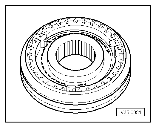
→ Fig.10 Dismantling and assembling 1st and 2nd gear locking collar and synchro-hub
The wide shoulder of the synchro-hub (arrow A) and the outer splines of the locking collar (arrow B) face opposite directions after assembly. Recesses for locking pieces on synchro-hub and locking collar must align. |
 |
|
|
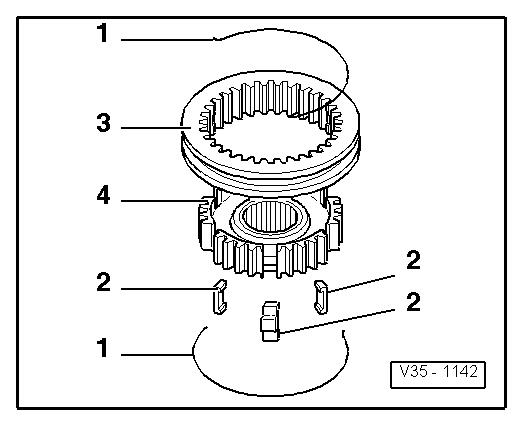
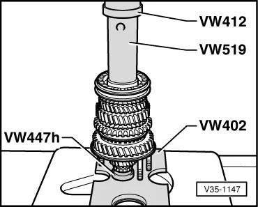
→ Fig.11 Assembling 1st and 2nd gear locking collar/synchro-hub
|
 |
|
|
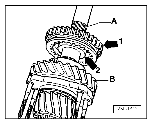
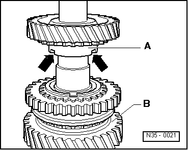
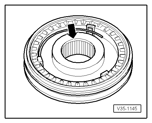
→ Fig.12 Installation position 1st and 2nd gear locking collar/synchro-hub The locking collar splines (arrow 1) point to splines for 3rd/4th gear synchro-hub -A-. The wide shoulder of the synchro-hub (arrow 2) then faces to 1st gear -B-. |
 |
|
|
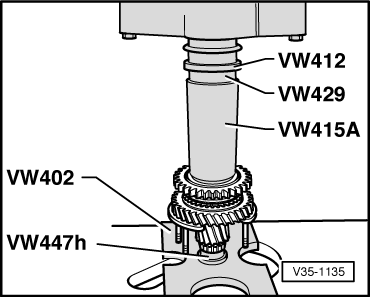
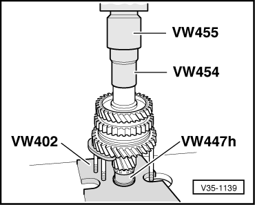
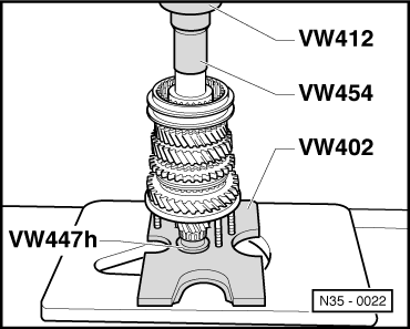
→ Fig.13 Pressing on 1st and 2nd gear locking collar/synchro-hub Note: Before pressing on, place 1st gear synchro-ring on 1st gear wheel. |
 |
|
|
→ Fig.14 Identifying 1st and 2nd gear synchro-rings
Only the version with 2 ground-down half teeth is available as a spare part for the 2nd gear synchro-ring. |
 |
|
|
→ Fig.15 Distinguishing 1st and 2nd gear synchro-rings
|
 |
|||||||
|
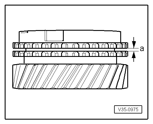
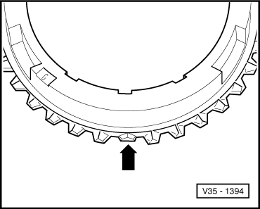
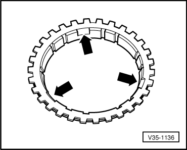
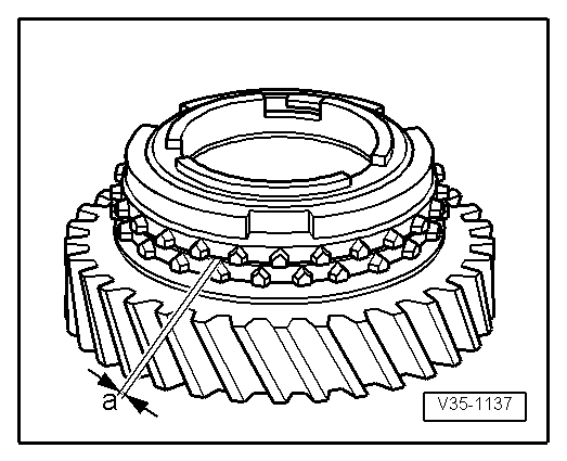
→ Fig.16 Checking 2nd gear synchro-ring for wear
|
 |
|
|
→ Fig.17 Installation position outer-ring The lugs (arrows) face to 1st gear -A- |
 |
|||||||
|
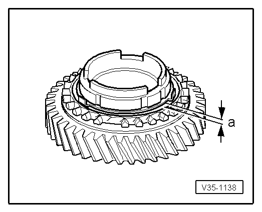
→ Fig.18 Checking inner ring for wear
|
 |
|
|
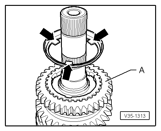
→ Fig.19 Installation position synchro-ring (inner-ring) -A- The lugs (arrow 1) locate in the recesses (arrow 2) in the synchro-ring -B-. |
 |
|
|
→ Fig.20 Installation position 2nd gear wheel The higher shoulder -A- faces to 1st gear -B-. The recesses in the shoulder (arrows) locate with the lugs of the outer-ring (arrow => Fig.17 ) |
 |
|
|
→ Fig.21 Pressing on needle roller bearing sleeve for 3rd gear |
 |
|
|
→ Fig.22 Dismantling and assembling 3rd and 4th gear locking collar and synchro-hub
The recesses for locking pieces in synchro-hub and locking collar must align. |
 |
|
|
→ Fig.23 Assembling 3rd and 4th gear locking collar/synchro-hub The locking collar has been pushed over the synchro-hub.
|
 |
|
|
→ Fig.24 Installation position 3rd and 4th gear locking collar/synchro-hub Chamfer (arrow) faces to 4th gear. |
 |
|
|
→ Fig.25 Pressing on 3rd and 4th gear synchro-hub with locking collar |
 |
|
|
→ Fig.26 Pressing on sleeve for 4th gear needle roller bearing |
 |
|
|
→ Fig.27 Pressing on sleeve for output shaft needle roller bearing |