volkswagen Workshop Repair Guides

Volkswagen Workshop Service and Repair Manuals

Locations of diagnosis connections > < Locations of electrical/electronic components
Automatic gearbox 001
Locations of electrical/electronic components
Components in vehicle
  • Automatic gearbox control unit -J217-
    • ◆ Location
    • ◆ Removing => Page 37-7
    • ◆ Checked by self-diagnosis
  • Engine control unit
    • ◆ Location and removing and installing =>Fig. 1

If engine or gearbox control units are renewed, the system must be brought to basic setting.

  • ‒ Perform self-diagnosis and initiate basic setting.

=> Automatic gearbox 001 self-diagnosis; Repair group 01; Performing self-diagnosis; Initiating basic setting

 
N01-0270
  • Throttle valve potentiometer -G69-, or accelerator position sender -G79-
    • ◆ Further information => Fig. 2
  • Gearbox
    • ◆ Electrical/electronic components of the gearbox are described => from page 37-11
  • Diagnostic connection
    • Location on vehicles
    • ◆ up to ▸ 08.97 => page 37-9
    • ◆ 09.97 ▸ 09.99=> page 37-9
    • ◆ from 10.99 ▸ => page 37-10
  • Kickdown switch -F8-
    • ◆ Location, removing and installing => Fig. 3
    • ◆ Can be checked via electrical check

=> Automatic gearbox 001 self-diagnosis; Repair group 01; Gearbox: Electrical check

    • ◆ Not fitted in vehicles from 07.99
 
N01-0270
  • Brake light switch -F-
    • ◆ Location => Fig. 5
  • Starter inhibitor relay -J207-
    • ◆ Location => Fig.6
  • Solenoid for selector lever lock -N110-
    • ◆ Location, removing and installing

=> Repair group 37; Servicing gear selector lever

  • Cruise control switch -E45-
    • ◆ Location and removing and installing =>Fig. 4

Selector lever display -Y5- => Page 37-4

 
N01-0135

→ Selector lever display -Y5-

Location: Selector lever position display is located in combi-instrument.

Removing and installing selector lever position display.

=> Repair group 90; Removing and installing dash panel insert

In emergency running mode with the control unit functioning, all segments in the selector lever position display in the dash panel will light up.

In emergency running with a defective control unit there will be no display in the selector lever position display.

On vehicles with data bus, the display is controlled by the data bus diagnosis interface via the gearbox control unit.

 
N01-0138

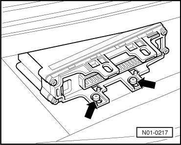
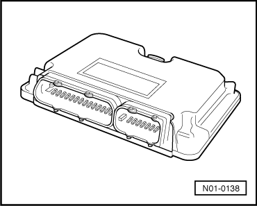
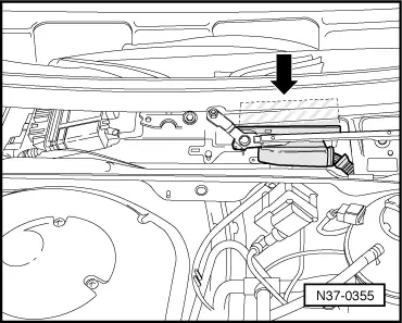
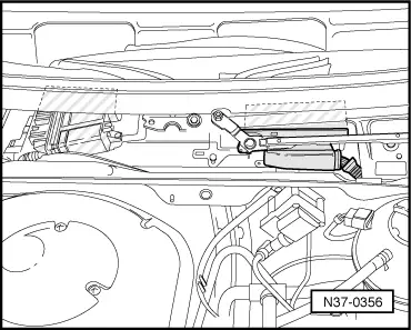
→ Fig.1     Engine control unit

Location: The control unit is located in plenum chamber.

Removing and installing control unit

=> Injection and ignition system; Repair group 24

 
N37-0157

→ Fig.2     Throttle valve potentiometer -G69- or throttle position sender -G79-

Locations:

The potentiometer is a component part of the throttle valve control part -J338-. It is located on the throttle valve housing (engine).

The throttle position sender -G79- is part of the electronic power control (EPC) and can be found on the foot pedal.

Checking and adjusting or removing and installing throttle valve potentiometer

On vehicles from 10.99, the switch signal comes from the data bus.

=> Repair group 24; depending on engine code

 
N01-0202

→ Fig.3     Kickdown switch -F8- (only on vehicles without data bus)

Location: Kickdown switch (arrow) is integrated into accelerator cable and is located on bulkhead in engine compartment.

On vehicles from 07.99, the switch signal comes from the data bus.

These vehicles have no switch.

The signal is generated in the "electronic accelerator" (EPC).

Removing and installing kickdown switch

 
N37-0285
  • ‒ Remove the accelerator cable to remove and install the kickdown switch, then reinstall cable and adjust.

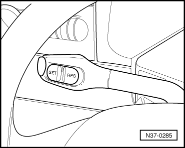
=> Repair group 20; Servicing accelerator mechanism; Adjusting accelerator cable

→ Fig.4     Cruise control system switch -E45-

Location: Cruise control switch is located on steering column switch.

Removing and installing cruise control switch

=> Electrical system; Repair group 94

 
N01-0206

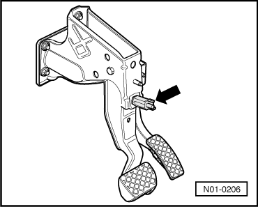
or

=> Electrical system; Repair group 96

On vehicles from 07.99, the switch signal comes from the data bus.

→ Fig.5     Brake light switch -F-

Location: Brake light switch (arrow) is located on pedal cluster.

Removing and installing brake light switch

=> Running gear self-diagnosis for ABS; Repair group 01; Electrical/electronic components and Fitting locations.

On vehicles from 07.99, the switch signal comes from the data bus.

 
N37-0357

→ Fig.6     Starter inhibitor relay -J207-

Location: The relay is located on relay carrier behind the fuse holder below the dash panel.

Relay is marked with number "53" (arrow).

Assignment

=> "Current flow diagrams, Electrical fault finding and Fitting locations" binder, Polo 1995 ▸

  • ‒ The relay can be identified via connecting cable colours.
 
N37-0355

Location of control unit for automatic gearbox -J217-

→ The control unit (arrow) is located in the plenum chamber.

Removing control unit

  • ‒ Switch off ignition, open bonnet.
  • ‒ Remove wiper arms and cowl panel:
 
N37-0356

=> Electrical system; Repair group 94; Windscreen wiper system; Removing and installing windscreen wiper system

  • ‒ Partially remove/install wiper rods.
  • ‒ → Remove engine control unit.

Location: The control unit is located in plenum chamber.

=> Repair group 24

 
N01-0217
  • ‒ Release multi-pin connector and pull off control unit.
  • ‒ → Remove screws -arrows-.
  • ‒ Remove control unit.

Installing control unit

Installation is performed in the reverse order.

  • ‒ Perform self-diagnosis and initiate basic setting.

=> Automatic gearbox 001 self-diagnosis; Repair group 01; Performing self-diagnosis; Initiating basic setting

Locations of diagnosis connections > < Locations of electrical/electronic components