
Polo Mk3
|
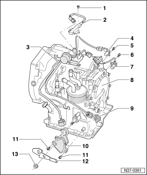
Locations of electrical/electronic components
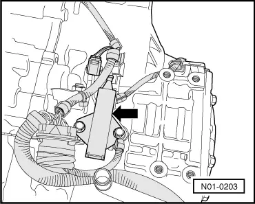
Components on gearbox
|
 |
|
=> Automatic gearbox 001 self-diagnosis; Repair group 01; Performing self-diagnosis |
|
|
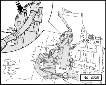
=> Automatic gearbox 001 self-diagnosis; Repair group 01; Performing self-diagnosis
|
|
|
=> Automatic gearbox 001 self-diagnosis; Repair group 01; Performing self-diagnosis
|
 |
|
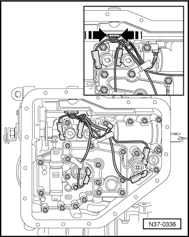
Installation is performed in the reverse order. Sequence for dismantling and assembling => from page 37-94 . Observe instructions for dismantling and assembling planetary gearbox. The cable colours are the same as the relevant solenoid valve colours. |

 |
|
Installation is performed in the reverse order.
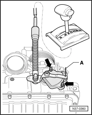
→ Fig.3 Adjusting multi-function switch Prerequisites
Vehicles from 06.99 => page 37-29 Vehicles from 07.99 => page 37-30
|
 |
|
|
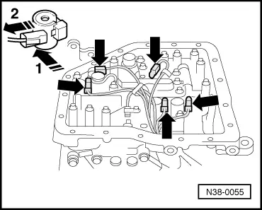
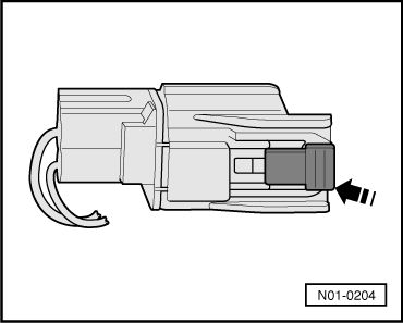
Series resistor connector must be pulled off to measure resistance.
|
 |
|
|