volkswagen Workshop Repair Guides

Volkswagen Workshop Service and Repair Manuals

Dismantling and assembling selector mechanism on vehicles with ignition key removal lock from 06.99 > < Checking and adjusting selector lever cable on vehicles from 07.99
Automatic gearbox 001
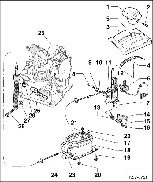
Servicing gear change mechanism
Dismantling and assembling selector mechanism on vehicles without key withdrawal lock up to 06.99
 
N37-0751
  • Selector lever handle
  • Set screw, 1.5 Nm
  • Cover
    • ◆ With selector indicator
  • Cover strip
    • ◆ Insert into cover -Fig. 3 -
  • Protective sleeve for selector lever
 
N37-0751
  • Selector lever lock solenoid -N110-
    • ◆ Adjusting => Fig. 3
    • ◆ Functional check => Fig. 4
    • ◆ Securing wiring loom to selector housing => Fig. 6
    • ◆ Can be checked electrically and by measured value block

=> Self-diagnosis for automatic gearbox 001; Repair group 01; Performing self-diagnosis; Reading measured value block

  • Bolt, 3 Nm
    • ◆ Qty. 2
    • ◆ Insert with AMV 185 101 A1
  • Combi-bolt
    • ◆ Grease shank
  • Bush
  • Locking washer
    • ◆ Installing => Fig. 5
 
N37-0751
  • Selector lever
    • ◆ To remove, remove catalyst and forward protective plate.
    • ◆ Assemble before installing => Fig. 2
  • Indicator lighting
    • ◆ Securing indicator lighting connector => Fig. 7
    • ◆ On right-hand drive vehicles there is an additional contact which prevents starting the engine when the "selector lever handle" locking button has been pressed
  • Spring
    • ◆ Insert together with lever -Fig. 14 - into selector lever
  • Lever
    • ◆ To lock in selector lever position "P" or "N"
  • Bush
  • Nut, 10 Nm
    • ◆ Always renew
 
N37-0751
  • Gasket
  • Selector lever housing
    • ◆ Need not be removed to replace selector lever cable or individual parts of selector mechanism
    • ◆ Removing => Fig. 1
  • Combi-bolt, 25 Nm
    • ◆ Qty. 4
  • Nut, 15 Nm
    • ◆ Qty. 3
    • ◆ Always renew
  • Distance piece
  • Nuts
    • ◆ To secure central console
  • Protective sleeve
    • ◆ Insert into selector lever housing before attaching selector lever cable =>Fig. 8
 
N37-0751
  • Selector lever cable
    • ◆ To remove, remove catalyst and forward protective plate.
    • ◆ Do not bend or kink , lightly grease cable eyelet and cable ends before installing
    • ◆ Check guide tube for tight fit
    • ◆ Check that protective sleeve between console and lever/selector shaft is correctly located and secure selector lever cable with corrugated locking element
    • ◆ Securing selector lever cable to selector lever => Fig. 5
    • ◆ Adjusting
 
N37-0751
  • Gearbox
  • Lever
    • ◆ For selector shaft
  • Washer
  • Combi-bolt, 23 Nm
  • Corrugated locking element
    • ◆ For selector lever cable
    • ◆ Always renew
 
N37-0358

→ Fig.1     Removing selector lever housing

  • ‒ Remove rear centre console.
  • ‒ Pull off Lambda probe connector, separate exhaust system at catalyst, remove catalyst.
  • ‒ Remove front protective plate and bolts (arrows).
 
N37-0068

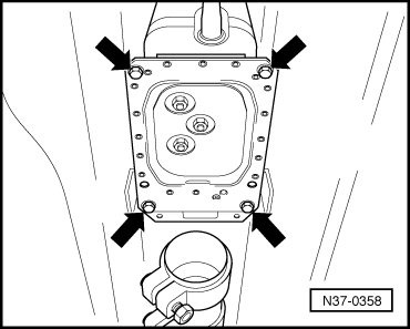
→ Fig.2     Assembling selector lever before installing

Before installing selector lever in selector lever housing adjust selector lever lock solenoid -N110- => Fig. 3 and carry out functional check => Fig. 4 .

  • ‒ Install set screw and selector lever lock solenoid -N110- screw with locking fluid AMV 185 101 A1.
 
N37-0083

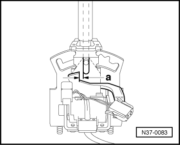
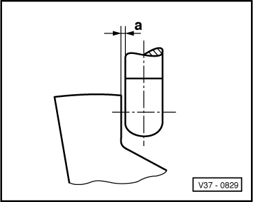
→ Fig.3     Adjusting selector lever lock solenoid -N110-

  • ‒ Adjust solenoid by sliding in elongated holes so that a clearance -a- of 0.3 mm exists between pressure rod and lever => Fig. 4 .
 
V37-0829

→ Fig.4     Adjusting clearance between pressure rod and lever

Dimension a = 0.3 mm

Functional check

  •      1 -     Shift selector lever into "P" and supply solenoid with 12 V. It must not be possible to shift lever into a driving gear.
  •      -     Interrupt solenoid operation; it must be possible to shift into all driving gears.
  •      -     Pressure rod must not catch on lever.
  •      2 -     Shift selector lever into "N" and check as in 1.
  •      -     After adjusting clearance, install assembled selector lever.
 
N37-0070

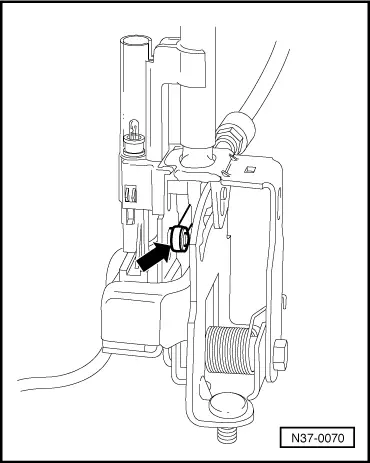
→ Fig.5     Securing selector lever cable to selector lever

  • ‒ Fit selector lever cable eye (arrow) on selector lever and secure with circlip.
 
N37-0067

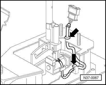
→ Fig.6     Securing wiring loom to selector lever housing

  • ‒ Press wiring loom into clips and into selector lever housing (arrows).
 
N37-0072

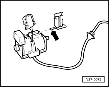
→ Fig.7     Securing indicator lighting connector

  • ‒ Push bracket with lug (arrow) on until lug engages.
  • ‒ Seat connector cable into bracket and slide connector onto bracket.
 
N37-0141

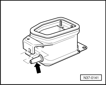
→ Fig.8     Insert boot in selector lever housing

  • ‒ Before installing the selector lever cable insert boot (arrow).

Dismantling and assembling selector mechanism on vehicles with ignition key removal lock from 06.99 > < Checking and adjusting selector lever cable on vehicles from 07.99