volkswagen Workshop Repair Guides

Volkswagen Workshop Service and Repair Manuals

Read measured value block and basic settings > < Fault table
1AV fuel injection and ignition system (2-valve)
Self diagnosis
Final control diagnosis

The final control diagnosis activates the following components in the stated sequence:

1. Throttle valve positioner (V60)

2. Activated charcoal filter solenoid valve 1 (N80)

3. Engine speed signal

4. Fuel pump relay (J17)

5. Engine/air conditioner compressor electrical connection

Special tools, testers, measuring instruments and auxiliary items required

  • ◆ Fault reader V.A.G 1551 or vehicle system tester V.A.G 1552 with cable V.A.G 1551/3
  • ◆ Test box V.A.G 1598/18
  • ◆ Hand multimeter V.A.G 1526 or multimeter V.A.G 1715
  • ◆ Diode test lamp V.A.G 1527
  • ◆ Adapter set V.A.G 1594
  • ◆ Current flow diagram

Check conditions

  • ● Throttle valve potentiometer (G69) OK.
  • ● Fuses 15, 18 and 21 OK.

Test requirements for vehicles with air conditioning system

  • ● Vehicle at room temperature (warmer than + 15 °C)
  • ● Air conditioning system switched on
  • ● Select lowest temperature and highest blower speed

Notes:

If the final control diagnosis is to be repeated without the engine being started in between time, switch ignition off for approx. 20 seconds.

Work sequence

  • ‒ Connect the fault reader V.A.G 1551 (V.A.G 1552). Then switch ignition on and select engine control unit with the "Address word" 01.
    (Connecting fault reader and selecting engine control unit .)
 
→ Indicated on display:
Rapid data transfer     HELP
Select function XX
  • ‒ Operate fault reader taking into account the information on the display:
  • ‒ Press keys 0 and 3 for the function "Final control diagnosis".
 
→ Indicated on display:
Rapid data transfer     Q
03 Final control diagnosis

Activate throttle valve positioner (V60):

  • ‒ Confirm input with Q key.
 
→ Indicated on display:
Final control diagnosis     ⇒
Throttle valve positioner-V60
  • The throttle valve positioner must open and close the throttle valve until switching to the next final control by pressing the ⇒key.

If the throttle valve positioner does not move:

  • ‒ Check throttle valve positioner
    , checking throttle valve control part

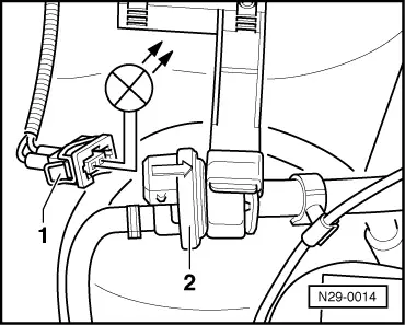
Activate solenoid valve 1 for activated charcoal filter (N80):

  • ‒ Press ⇒key.
 
→ Indicated on display:
Final control diagnosis     ⇒
Activ. charcoal filter solenoid valve 1     -N80
  • The solenoid valve (right-hand suspension turret) must click, until activating the next final control element by pressing ⇒key.
  • ‒ Pull hose off activated charcoal filter at solenoid valve.
  • ‒ Connect an auxiliary hose to the vacant valve connection.
  • ‒ Blow into auxiliary hose during final control diagnosis (in direction of throttle valve control part).
         Valve must open and close

If the solenoid valve does not click:

  • ‒ Continue check => Page 01-30 .

Display engine speed signal:

Note:

The test is only possible for vehicles with a rev. counter. On vehicles without rev. counter switch to the next final control by pressing the ⇒ key.

  • ‒ Press ⇒key.
 
→ Indicated on display:
Final control diagnosis     ⇒
Engine speed signal

The rev. counter must display approx. 3000 rpm, until next final control element is activated by pressing the ⇒key.

If no display appears:

  • ‒ Check the rev. counter.

=> Current flow diagrams, Electrical fault finding and Fitting locations, Fuel supply system

Actuate fuel pump relay (J17):

  • ‒ Press ⇒key.
 
→ Indicated on display:
Final control diagnosis     ⇒
Fuel pump relay J17
  • The fuel pump relay (on the relay plate with fuse box, relay position 12) must click until switching to the next final control by pressing the ⇒key.

Note:

During the activation of the fuel pump relay the fuel pump must be heard to run at intervals.

If the relay does not click:

  • ‒ Check fuel pump relay:

=> Current flow diagrams, Electrical fault finding and Fitting locations, Fuel supply system

Check electrical connection to air conditioner:

Note:

The test step is only for vehicles with air conditioner. On vehicles without air conditioner end final control diagnosis by pressing ⇒key.

 
→ Indicated on display:
Final control diagnosis     ⇒
Engine/air cond. compr. electr. connection
  • The air conditioner compressor magnetic coupling must click, until ending final control diagnosis by pressing ⇒key.

If the magnetic coupling does not click:

  • ‒ Check air conditioner.

=> Heater, air conditioner

  • ‒ Press ⇒key.
 
→ Indicated on display:
Rapid data transfer     HELP
Select function XX
  • ‒ Press keys 0 and 6 for the function "End output" and confirm entry with the Q key.
  • ‒ Switch off ignition.

Note:

After completion of the final control diagnosis switch off ignition. If the ignition is not switched off before attempting to start, the engine will not run, as the injectors and the ignition transformer will not be activated.

Continuation of check when the activated charcoal filter solenoid 1 does not click:

 
N29-0014
  • ‒ → Pull connector -1- off solenoid valve -2- and connect diode test lamp V.A.G 1527 with aux. cables from V.A.G 1594 to disconnected connector.
         The LED must flash (bright/darker)

LED flashes:

  • ‒ Proceed with final control diagnosis until completed.
  • ‒ Switch off ignition.
  • ‒ Renew solenoid valve -2-.

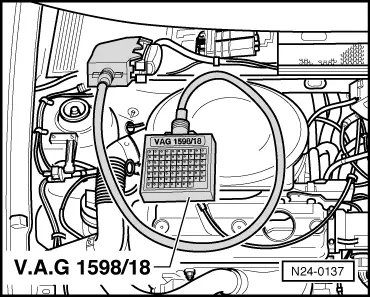
=> Repair group 20; Removing and installing parts of activated charcoal filter system

LED does not flash:

 
N24-0137
  • ‒ Proceed with final control diagnosis until completed.
  • ‒ Switch off ignition.
  • ‒ → Connect test box V.A.G 1598/18 to control unit wiring loom.
  • ‒ Check wire for open circuit between test box sockets 3 and 2 pin connector contact 1, according to current flow diagram.
         Wire resistance: max. 1.5 ω
  • ‒ Additionally check wire for short to battery positive and earth.
         Specification: ∞ω
  • ‒ Check wire between 2 pin connector contact 2 and relay plate for open circuit using to current flow diagram.
         Wire resistance: max. 1.5 ω

If no wiring fault is detected:

  • ‒ Renew engine control unit
    => Page 24-11 , item 30

Read measured value block and basic settings > < Fault table