Polo Mk3
 Note
Note
|
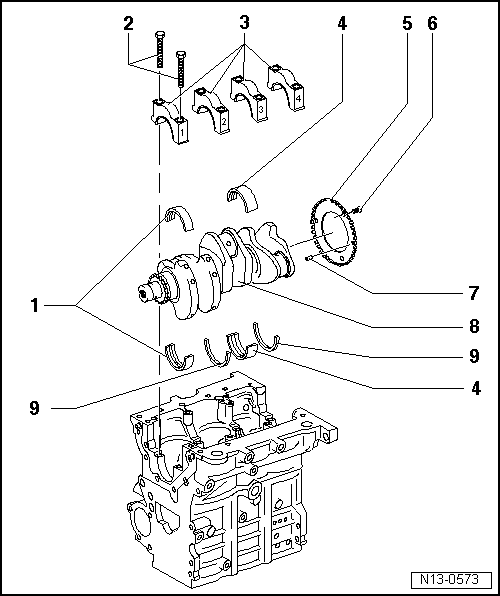
| 1 - | Bearing shells 1, 2 and 4 |
| q | For bearing cap without oil groove. |
| q | For cylinder block with oil groove |
| q | Do not interchange used bearing shells (mark). |
| 2 - | 65 Nm + 1/4 turn (90°) further |
| q | Renew |
| q | To measure radial clearance, tighten to 65 Nm but not further. |
| 3 - | Bearing cap |
| q | Bearing cap 1: belt pulley end. |
| q | Bearing shell retaining lugs in cylinder block and bearing caps must align. |
| 4 - | Bearing shell 3 |
| q | For bearing cap without oil groove. |
| q | For cylinder block with oil groove |
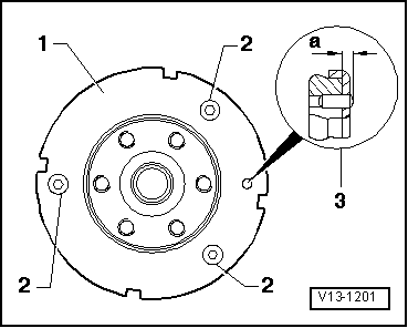
| 5 - | Sender wheel |
| q | For speed sender |
| q | Renew if damaged. |
| 6 - | 10 Nm + 1/4 turn (90°) further |
| q | Renew |
| 7 - | Dowel pin |
| q | Check projection from crankshaft → Fig. |
| 8 - | Crankshaft |
| q | Before removing, see note → Chapter |
| q | Axial clearance. |
| q | New: 0.07…0.17 mm |
| q | Wear limit: 0.37 mm |
| q | Check radial clearance with Plastigage. |
| q | New: 0.03…0.08 mm |
| q | Wear limit: 0.17 mm |
| q | Do not rotate crankshaft when checking radial clearance. |
| q | Crankshaft dimensions → Chapter. |
| 9 - | Thrust washer |
| q | For cylinder block, bearing 3 |