volkswagen Workshop Repair Guides

Volkswagen Workshop Service and Repair Manuals

Ignition system, glow plug system > < Checking exhaust gas recirculation valve
Checking exhaust gas recirculation
   
Checking exhaust gas recirculation
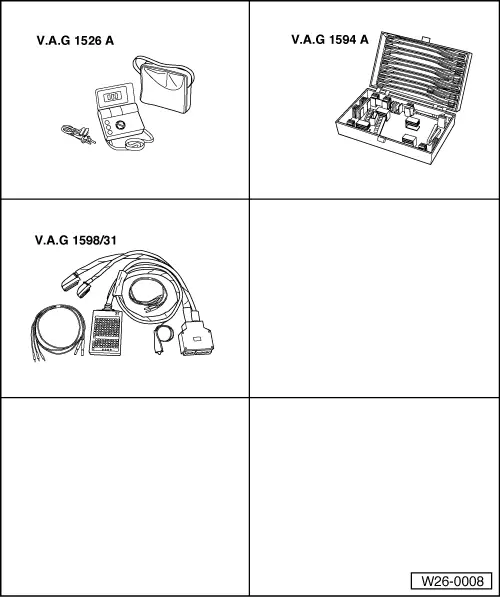
Special tools and workshop equipment required
t  Hand multimeter -V.A.G 1526A- or hand multimeter -V.A.G 1526C-
t  Auxiliary measuring set -V.A.G 1594A- or auxiliary measuring set -V.A.G 1594C-
t  Adapter cable, 121-pin -V.A.G 1598/31-
t  Fault reader -V.A.G 1551-
t  Diagnosis lead -V.A.G 1551/3C-
t  Current flow diagram

Test procedure
The exhaust gas recirculation function is checked in function 04 (basic setting). Using this method the exhaust gas recirculation valve -N18- is pulsed every 10 seconds, so that the extreme values for exhaust gas recirculation (air mass meter) can be read in display zone 3 in measured value block 003.
–  Connect fault reader -V.A.G 1551- and select engine electronics control unit with “address word 01”. Engine must be idling.
   
Indicated on display:
–  Press buttons 0 and 4 for function “Initiate basic settings” and confirm entry with Q button.
 
Rapid data transfer                 HELP
Select function XX                      
Indicated on display:
–  Press buttons 0, 0 and 3 for “display group number 3” and confirm entry with Q button.
  Note
When display group 3 is selected and confirmed with Q button, the idling speed in display zone 1 will be raised by the engine control unit to 1350...1450 rpm.
 
Basic setting                       HELP
Input display group number XXX          
Indicated on display: (1...4 = display zones)
The display in display zone 2 must fluctuate every 10 secs. between EGR active and EGRn. active.
The displays in display zones 3 and 4 must fluctuate within following control range:
  Note
If a constant value of 539 mg/H is displayed in display zone 3, check air mass meter -G70-: → Chapter
EGRn. active
–  Specification display zone 3: 450...600 mg/H (stroke).
–  Specification display zone 4: 20 %
EGR active
–  Specification display zone 3: 160...310 mg/H (stroke).
–  Specification display zone 4: 65 %
If the specifications are not attained:
–  Check mechanical exhaust gas recirculation valve → Chapter
–  Check vacuum hoses → Chapter.
–  Check exhaust gas recirculation valve -N18- as follows:
–  Press the button.
–  Press buttons 0 and 6 for function “End data transfer” and confirm entry with Q button.
–  Switch off ignition.
 
System in basic setting 3             ->
   1400 rpm EGRn.active   500 mg/H   20%
–  Pull connector off exhaust gas recirculation valve -N18-.
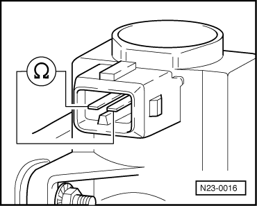
–  Measure resistance at valve. Specification: 14...20 Ω
If the specification is not attained:
–  Renew exhaust gas recirculation valve -N18-
  Note
At room temperature the resistance is in the lower tolerance range and at operating temperature in the upper tolerance range.
If the specification is attained:
–  Switch on ignition.
  N23-0016
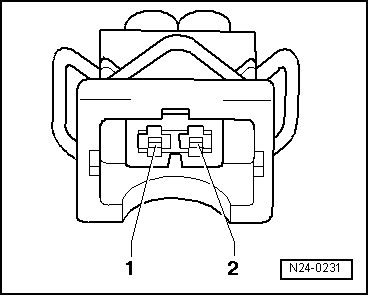
–  Measure supply voltage at valve connector contact 1 and at engine earth. Specification: approx. battery voltage
If the specification is not attained:
–  Switch off ignition.
  N24-0231
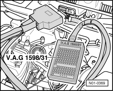
–  Connect adapter cable, 121-pin -V.A.G 1598/31- to control unit wiring harness.
–  Check wiring between adapter cable, 121-pin -V.A.G 1598/31- and connector for open circuit referring to current flow diagram.
Contact 1 + socket 1 + 2
Contact 2 + socket 61
Wire resistance: max. 1.5 Ω.
–  Also check wiring for short to one another, short to vehicle earth and short to battery positive.
Specification: ∞ Ω.
If no fault in lines is detected:
–  Renew diesel direct injection system control unit -J248- → Chapter.
  N01-0369

Ignition system, glow plug system > < Checking exhaust gas recirculation valve