volkswagen Workshop Repair Guides

Volkswagen Workshop Service and Repair Manuals

Checking intake manifold flap change-over > < Checking fuel temperature sender G81
Checking air mass meterG70
Checking air mass meter -G70-
The air mass meter signal is used by the control unit to calculate the quantity injected and to control the required exhaust gas recirculation. The smaller the signal from air mass meter -G70- the smaller the quantity of fuel injected.
Special tools and workshop equipment required
t  Fault reader -V.A.G 1551-
t  Diagnosis lead -V.A.G 1551/3C-
t  Adapter cable, 121-pin -V.A.G 1598/31-
t  Hand multimeter -V.A.G 1526C- or multimeter -V.A.G 1715-
t  Auxiliary measuring set -V.A.G 1594C-
t  Current flow diagram
Test procedure
–  Connect fault reader -V.A.G 1551- and select engine electronics control unit with “address word 01”. Engine must be idling. (Connecting fault reader and selecting engine electronics control unit → Chapter.)
  WARNING
Secure fault reader to rear seat and operate from this position.
   
Indicated on display:
–  Press buttons 0 and 8 for function “Read measured value block” and confirm entry with Q button.
 
Rapid data transfer                 HELP
Select function XX                      
Indicated on display:
–  Press buttons 0, 1 and 0 for “display group number 10” and confirm entry with Q button.
–  Observe display in display zone 1.
 
Reading measured value block          ->
Input display group number XXX          
–  Specification: 200...320 mg/H
If the specification is not attained:
–  Check exhaust gas recirculation → Chapter.
If the specification is attained:
–  Accelerate vehicle from approx. 1500 rpm using full throttle.
–  At approx. 3000 rpm, press PRINT button on fault reader -V.A.G 1551-. Accelerator pedal must be fully depressed at this moment.
 
Read measured value block 10          ->
209 mg/H   1027 mbar   1011 mbar  0.0 %
–  Specification in display zone 4: 100 % (accelerator pedal position)
If the specification is not attained:
–  Repeat test and accelerate vehicle at full throttle.
 
Read measured value block 10          ->
830 mg/H   1027 mbar   1850 mbar  100 %
–  Specification in display zone 1 (mass of air drawn in): above 700 mg/H
If the specification is not attained:
–  Renew air mass meter -G70-.
If a constant 539 mg/H (predetermined replacement value) is displayed in display zone 1.
–  Press the button.
–  Press buttons 0 and 6 for function “End output” and confirm entry with Q button.
–  Switch off ignition.
–  Separate connector for air mass meter -G70- → Chapter.
–  Switch on ignition.
 
Read measured value block 10          ->
830 mg/H   1027 mbar   1850 mbar  100 %
–  Measure voltage supply for air mass meter -G70- between following connector contacts:
  N24-0642
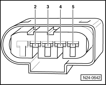
Connector on air mass meter -G70-
contact
Specification
2 + earthApp. battery voltage
2 + 3App. battery voltage
4 + earthApprox. 5 V
4 + 3Approx. 5 V

If the specifications are not attained:
–  Switch off ignition.
   
–  Connect adapter cable, 121-pin -V.A.G 1598/31- to control unit wiring harness.
–  Check wiring between adapter cable, 121-pin -V.A.G 1598/31- and connector for open circuit referring to current flow diagram.
Contact 2 + socket 1 and 2
Contact 3 + socket 49
Contact 4 + socket 30
Contact 5 + socket 68
  N23-0377
Wire resistance: max. 1.5 Ω.
–  Also check wiring for short to one another, short to vehicle earth and short to battery positive.
Specification: ∞ Ω.
If no fault in lines is detected:
–  Renew diesel direct injection system control unit -J248- → Chapter.
  N24-0642

Checking intake manifold flap change-over > < Checking fuel temperature sender G81