The clutch pedal switch -F36- informs the control unit whether the clutch is engaged or disengaged. If the clutch is being operated the injected quantity is momentarily reduced. This prevents engine jerks.
Special tools and workshop equipment required
t
Fault reader -V.A.G 1551-
t
Diagnosis lead -V.A.G 1551/3C-
t
Adapter cable, 121-pin -V.A.G 1598/31-
t
Hand multimeter -V.A.G 1526C- or multimeter -V.A.G 1715-
t
Auxiliary measuring set -V.A.G 1594C-
t
Current flow diagram
Test procedure
–
Connect fault reader -V.A.G 1551- and select engine electronics control unit with “address word 01”. The ignition must be switched on for this purpose. (Connecting fault reader and selecting engine electronics control unit → Chapter.)
Indicated on display:
–
Press buttons 0 and 8 for function “Read measured value block” and confirm entry with Q button.
Rapid data transfer HELP
Select function XX
Indicated on display:
–
Press buttons 0, 0 and 6 for “display group number 6” and confirm entry with Q button.
–
Observe display in display zone 2.
Reading measured value block ->
Input display group number XXX
Specification: 0 0 0
–
Operate clutch pedal. The left position must change to 1.
Read measured value block 6 ->
0 km/h 0 0 0 0.0 % 255
Specification: 1 0 0
If the specifications are not attained:
–
Press the → button.
–
Press buttons 0 and 6 for function “End data transfer” and confirm entry with Q button.
–
Switch off ignition.
–
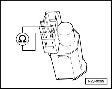
Pull connector off clutch pedal switch -F36- → Chapter.
Read measured value block 6 ->
0 km/h 1 0 0 0.0 % 255
–
Measure resistance at switch contacts. Specification Clutch not depressed: max. 10 Ω Clutch depressed: ∞ Ω
If the specifications are not attained:
–
Renew clutch pedal switch -F36-.
If the specifications are attained:
–
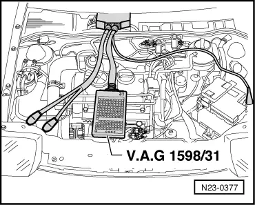
Connect adapter cable, 121-pin -V.A.G 1598/31- to control unit wiring harness.
–
Check wiring between test box and connector for open circuit referring to current flow diagram.
Contact 1 + socket 1
Contact 1 + socket 2
Contact 1 + socket 66
Wire resistance: max. 1.5 Ω.
–
Also check wiring for short to one another, short to vehicle earth and short to battery positive.
Specification: ∞ Ω.
If no fault in lines is detected:
–
Renew diesel direct injection system control unit -J248- → Chapter.