Hand multimeter -V.A.G 1526C- or multimeter -V.A.G 1715-
t
Auxiliary measuring set -V.A.G 1594C-
t
Current flow diagram
Test prerequisite
l
Fuses 23 and 27 OK.
Test procedure
–
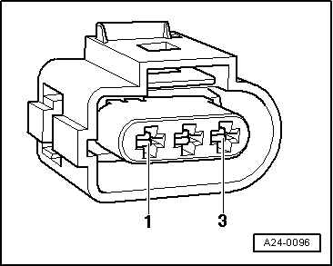
Pull 3-pin connector off Hall sender -G40- → Chapter.
–
Connect hand multimeter -V.A.G 1526C- using aux. cables from auxiliary measuring set -V.A.G 1594C- to measure voltage at contacts 1 (positive) and 3 (earth) of Hall sender -G40-.
–
Switch on ignition. Specification: Battery voltage
–
Switch off ignition.
If no voltage is present:
–
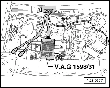
Connect adapter cable, 121-pin -V.A.G 1598/31- to control unit wiring harness.
–
Check wiring between adapter cable, 121-pin -V.A.G 1598/31- and 3-pin connector for open circuit referring to current flow diagram.
Contact 1 + socket 1/2
Contact 2 + socket 109
Contact 3 + socket 101
Wire resistance: max. 1.5 Ω.
–
Also check wiring for short to one another, short to vehicle earth and short to battery positive.
Specification: ∞ Ω.
If no wiring fault is detected and voltage was present between contacts 1 + 3: