-
‒ →
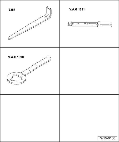
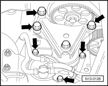
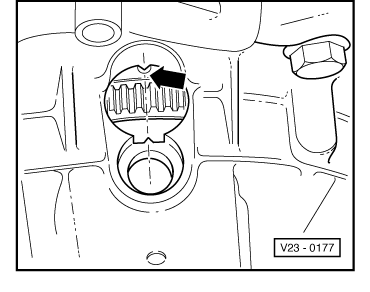
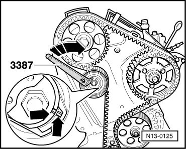
Turn tensioning roller with pin wrench 3387 to right until notch aligns with raised portion -arrows-.
Note:
If the eccentric has been turned too far the tensioning roller must be relieved completely and retensioned. The eccentric must never be turned back when it has been turned too far.
-
‒ Tighten lock nut on tensioning roller.
Tightening torque: 20 Nm
-
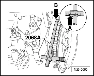
‒ Check again whether TDC mark on flywheel and reference mark are aligned.
-
‒ Tighten camshaft sprocket securing bolt to
45 Nm.
-
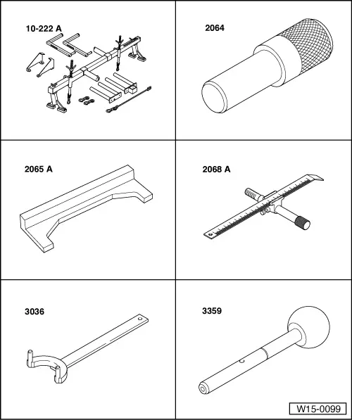
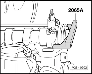
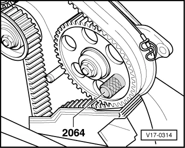
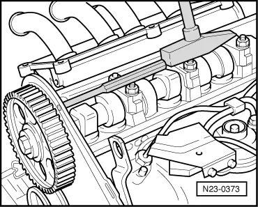
‒ Remove setting bar 2065 A from camshaft and mandrel 2064 from injection pump sprocket.
-
‒ Turn crankshaft two rotations in engine D.O.R. until crankshaft is set to TDC No. 1 cylinder again.
-
‒ Check if
the TDC mark on flywheel
the setting bar on camshaft
the mandrel 2064 in injection pump sprocket
the tensioning roller setting (notch/raised mark)
align/are fitted correctly.
-
‒ If notch and raised mark do not align, tension the tensioning roller. To do this, hold tensioning roller with pin wrench 3387, loosen securing nut, turn eccentric clockwise further until notch and raised mark align opposite one another and tighten securing nut to 20 Nm.
-
‒ Turn crankshaft two rotations in engine D.O.R. until crankshaft is set to TDC No. 1 cylinder again.
-
‒ Repeat check.
-
‒ Install toothed belt guard, vibration damper (note fixing), V-belt pulley tensioning roller, coolant belt pulley and cylinder head cover.
-
‒ Fit engine mounting to cylinder block.
Tightening torque: 45 Nm
-
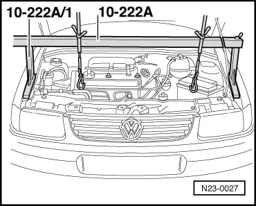
‒ Install engine assembly mounting.
Tightening torque => Page 10-11
.
-
‒ Install ribbed belt => Page 13-13
.
-
‒ Install noise insulation tray.
-
‒ Install connecting hose for air cleaner/air intake connecting piece.
-
‒ Install pendulum support free of tension.
Tightening torque assembly mountings
=> Page 10-11
.
-
‒ Checking injection pump commencement of delivery:
=> Repair group 23; Servicing Diesel direct injection system; Dynamically checking and adjusting commencement of delivery
Belt drive with two part injection pump sprocket
Removing
|