
Polo Mk3
|
Accelerator mechanism: 10.99 > (Engine codes AGD, AKU, ASX)
Checking accelerator pedal position sender
|
 |
|
|
Check conditions
Test sequence
|
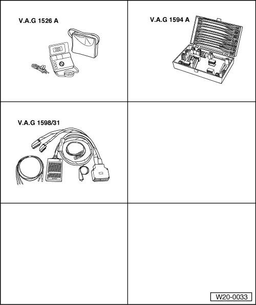
| → Indicated on display: |
|
||
|
| → Indicated on display: |
|
||
|
|
→
Check accelerator pedal position display in display zone 2. The accelerator pedal must not be depressed. Specification: 0.0 % |
|
||
|
Display: 0 1 0 |
| → Slowly depress accelerator pedal until fully down and observe display zones 2 and 3. |
|
||
End specification value not achieved:
=> Repair group 01; Self-diagnosis; Interrogating fault memory Display does not change or is erratic:
|
 |
|
|
 |
|
If no fault is detected in the wiring:
=> Repair group 01; Self-diagnosis; Interrogating fault memory |