
Polo Mk3
|
Removing and installing engine
Notes on removing
Note: Check whether a coded radio is installed as during the forthcoming work sequences the battery earth strap must be disconnected. Obtain radio code first if necessary.
=> Repair group 24; Servicing injection; Dismantling and assembling air cleaner
Warning!
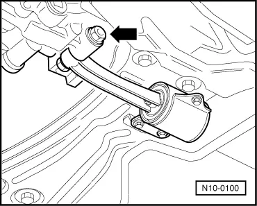
Fuel supply lines are under pressure! Before removing from hose connection wrap a cloth around the connection. Then release pressure by carefully pulling hose off connection.
|
 |
|
Vehicles with manual gearbox
=> Repair group 30; Servicing hydraulic clutch control
=> Repair group 34; Servicing gear change mechanism Vehicles with automatic gearbox
=> Repair group 37; Servicing selector mechanism; Dismantling and assembling selector mechanism Continuation for all vehicles
Vehicles with air conditioner
Continuation for all vehicles
=> General body repairs exterior; Repair group 50; Body front; Assembly overview |
 |
|
|
Vehicles with manual gearbox
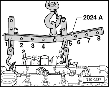
Pulley end:
Flywheel end: Warning!
The hooks and locating pins must be secured with locking pins. Notes:
Vehicles with automatic gearbox |
 |
|
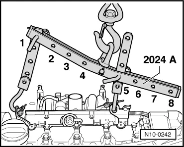
Flywheel end: Warning!
The hooks and locating pins must be secured with locking pins. Notes: |
 |
|
Vehicles with manual gearbox
|
 |
|
|
Vehicles with automatic gearbox
Continuation for all vehicles
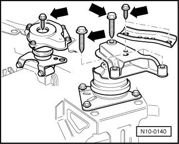
Note: When the assembly is lifted off, it must be carefully guided to prevent damage to the bodywork. |