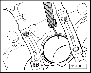
volkswagen Workshop Repair Guides

Volkswagen Workshop Service and Repair Manuals

Piston and cylinder dimensions > < Crankshaft dimensions
4-Cyl. injection engine (2 valve, roller rocker finger), Mechanics
Dismantling and assembling pistons and conrods
 
N13-0450
  • Circlip
  • Piston pin
    • ◆ If difficult to remove, heat piston to 60 °C
    • ◆ Remove and install with 10-14
  • Piston
    • ◆ Checking => Fig. 3
    • ◆ Mark installation position and cylinder number
    • ◆ Arrow on piston crown points to pulley end
    • ◆ Install using piston ring clamp
 
N13-0450
  • Compression rings
    • ◆ Offset gaps by 120 °
    • ◆ Remove and install compression rings with piston ring pliers
    • ◆ "TOP" faces towards piston crown
    • ◆ Checking ring gap=> Fig. 1
    • ◆ Checking ring to groove clearance
      => Fig. 2
  • Oil scraper ring
    • ◆ Remove and install spiral-type expander carefully by hand
    • ◆ "TOP" faces towards piston crown
    • ◆ Checking ring gap=> Fig. 1
    • ◆ Checking ring to groove clearance
      => Fig. 2
  • Conrod
    • ◆ Only renew as a set
    • ◆ Mark cylinder number -A-
    • ◆ Installation position:
      Marking -B- faces towards pulley end
    • ◆ Guided axially via piston
 
N13-0450
  • Conrod bearing cap
    • ◆ The caps only fit in one position and only on the appropriate con-rod, this is due to the breaking procedure (cracking) separating the cap from the con-rod
  • Conrod bolt, 20 Nm + 1/4 turn (90 °) further
    • ◆ Renew
    • ◆ Oil threads and contact surface
    • ◆ To measure radial clearance tighten to 20 Nm but not further
  • Bearing shell
    • ◆ Do not interchange used bearing shells
    • ◆ Insert bearing shells centrally
    • ◆ Check radial clearance with Plastigage:
      New: 0.020...0.061 mm
      Wear limit: 0.091 mm
      Do not rotate crankshaft when checking radial clearance
 
N13-0450
  • Cylinder block
    • ◆ Checking cylinder bores
      =>Fig. 4
    • ◆ Piston and cylinder dimensions
 
V13-0016

→ Fig. 1     Checking piston ring gap

  • ‒ Push ring squarely from above down to approx. 15 mm from bottom end of cylinder.

Piston ring

Wear limit

Compression rings

1.0 mm

Oil scraper ring

1.0 mm

 
V13-0687

→ Fig. 2     Checking ring to groove clearance

Clean groove before check.

Piston ring

Wear limit

Compression rings

0.15 mm

Oil scraper ring

0.15 mm

 
V13-0010

→ Fig. 3     Checking piston

Special tools, workshop equipment, testers, measuring instruments and auxiliary items required

  • ◆ External micrometer 60...90 mm
  • ‒ Approx. 10 mm from lower edge and offset 90 ° to piston pin axis. Deviations from nominal dimensions
         max. 0.04 mm
  • Nominal dimension ; Piston and cylinder dimensions
 
V13-0280

→ Fig. 4     Checking cylinder bores

Special tools, workshop equipment, testers, measuring instruments and auxiliary items required

  • ◆ Internal dial gauge 50...100 mm
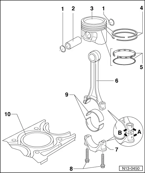
  • ‒ Take measurements at 3 positions in both lateral -A- and longitudinal -B- directions, as illustrated. Deviation from nominal dimension
         max. 0.08 mm
  • Nominal dimension => Page 13-50 ; Piston and cylinder dimensions

Note:

Measuring the cylinder bores must not be done when the cylinder block is mounted on a repair stand with adapter bracket VW 540, as incorrect measurements would then be possible.

Piston and cylinder dimensions > < Crankshaft dimensions