volkswagen Workshop Repair Guides

Volkswagen Workshop Service and Repair Manuals

Checking accelerator pedal position sender > < Servicing parts of electronic power control (EPC)
4-Cyl. injection engine (2 valve, roller rocker finger), Mechanics
Electronic power control (EPC)
Checking electronic accelerator warning lamp

Note:

The electronic accelerator warning lamp -K132 is known also as the EPC warning lamp.

Special tools, workshop equipment, testers, measuring instruments and auxiliary items required

  • ◆ Test box V.A.G 1598/22
  • ◆ Hand multimeter V.A.G 1526 or multimeter V.A.G 1715
  • ◆ Adapter set V.A.G 1594
  • ◆ Current flow diagram

Check conditions

  • ● The fuses must be OK.
  • ● The battery voltage must be at least 11.5 V.

Checking function of warning lamp

 
N01-0339
  • ‒ Switch on ignition.
  • → The EPC warning lamp must light up.
  • ‒ Start engine and run at idling speed.
  • The EPC warning lamp must
         go out
    when no EPC fault has been stored.
  • ‒ Switch off ignition.

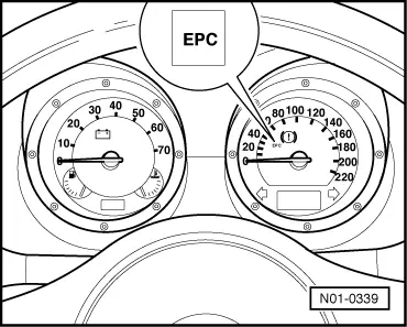
Electronic accelerator warning lamp does not light up

 
N24-0709
  • ‒ Remove wiper arms and cowl panel:

=> Electrical system; Repair group 92; Servicing windscreen wiper system

  • ‒ → Connect test box V.A.G 1598/22 to control unit wiring harness.
  • ‒ Bridge test box sockets 2 + 30 with aux. cables from V.A.G 1594.
  • ‒ Switch ignition on.
         The fault lamp must light up

If the fault lamp does not light up:

  • ‒ Switch off ignition.
  • ‒ Remove dash panel insert and check the bulb and its voltage supply.:

=> Electrical system; Repair group 90; Dash panel insert; Removing and installing dash panel insert

If no fault is found:

  • ‒ Check wiring for open circuit between test box socket 30 and dash panel insert using current flow diagram:

=> Current flow diagrams, Electrical fault finding and Fitting locations

If no wiring fault is detected:

  • ‒ Renew engine control unit:

=> Repair group 24; Engine control unit; Renewing engine control unit

Electronic accelerator fault lamp lights up continuously

 
N24-0709
  • ‒ → Connect test box V.A.G 1598/22 to control unit wiring harness.
  • ‒ Check wiring for short to earth between test box socket 30 and dash panel insert using current flow diagram:

=> Current flow diagrams, Electrical fault finding and Fitting locations

If no wiring fault is detected:

  • ‒ Renew engine control unit:

=> Repair group 24; Engine control unit; Renewing engine control unit

Checking accelerator pedal position sender > < Servicing parts of electronic power control (EPC)