
Polo Mk3
|
Removing and installing engine
Notes on removing
Note: Check whether a coded radio is installed as during the forthcoming work sequences the battery earth strap must be disconnected. Obtain radio code first if necessary.
Vehicles with accelerator cable
Continuation for all vehicles
=> Repair group 24; Servicing injection; Dismantling and assembling air cleaner
Warning!
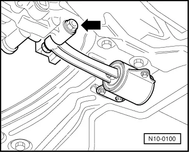
Fuel supply lines are under pressure! Before removing from hose connection wrap a cloth around the connection. Then release pressure by carefully pulling hose off connection.
|
 |
|
Vehicles with manual gearbox
=> Repair group 30; Servicing hydraulic clutch control
=> Repair group 34; Servicing gear change mechanism Vehicles with automatic gearbox
=> Repair group 37; Servicing selector mechanism; Dismantling and assembling selector mechanism Continuation for all vehicles
Vehicles with air conditioner
Continuation for all vehicles
=> Running gear; Repair group 40; Removing and installing drive shaft
Vehicles with manual gearbox |
 |
|
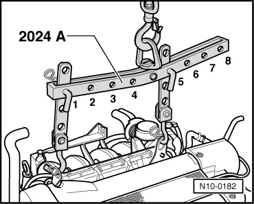
Pulley end:
Flywheel end: Warning!
The hooks and locating pins must be secured with locking pins. Notes:
|
 |
|
|
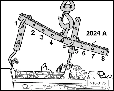
Vehicles with automatic gearbox
Flywheel end: Warning!
The hooks and locating pins must be secured with locking pins. Notes:
|
 |
|
|
Vehicles with manual gearbox
|
 |
|
|
Vehicles with automatic gearbox
Continuation for all vehicles
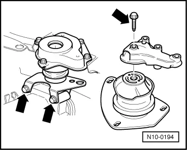
Note: When the assembly is lifted off, it must be carefully guided to prevent damage to the bodywork. |