volkswagen Workshop Repair Guides

Volkswagen Workshop Service and Repair Manuals

Reworking valve seats > < Removing and installing camshaft housing
4-Cyl. injection engine (4-valve, roller rocker arm), Mechanics
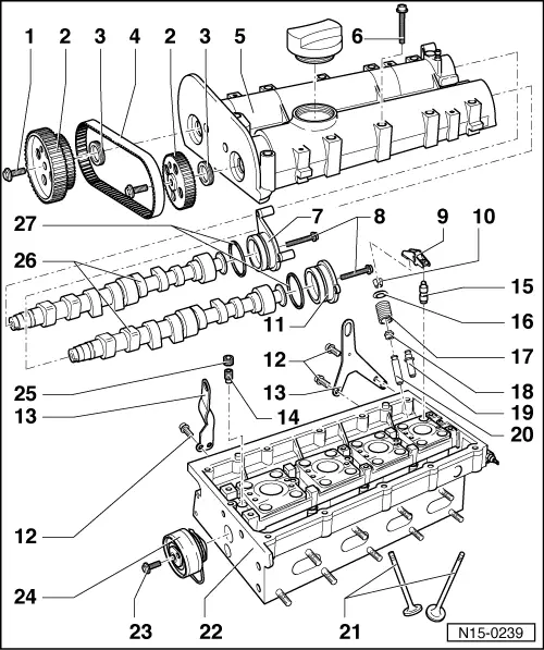
Servicing valve gear
 
N15-0239
  • 20 Nm + 1/4 turn (90 °) further
    • ◆ Renew
    • ◆ Use camshaft locking tool T 10016 to loosen and tighten , Fig.1
  • Camshaft sprocket
    • ◆ Note position when installing the toothed belt
  • Oil seal
    • ◆ Only replace with camshaft installed
    • ◆ Lightly oil sealing lip of oil seal
    • ◆ Renewing=> Page 15-34
  • Coupling drive toothed belt
    • ◆ Mark D.O.R. before removing
    • ◆ Check for wear
    • ◆ Do not kink
    • ◆ Removing and installing
      => Page 13-14
 
N15-0239
  • Camshaft housing
    • ◆ Removing and installing
      => Page 15-6
    • ◆ Remove sealant remnants
    • ◆ Coat with AMV 188 003 before fitting
    • ◆ When installing fit vertically from above onto studs and dowel pins
  • 10 Nm + 1/4 turn (90 °) further
    • ◆ Renew
    • ◆ Tighten from centre outwards
  • Sealing cap/ignition transformer retainer
  • 10 Nm
  • Roller rocker finger
    • ◆ Check roller bearing
    • ◆ Oil contact surface
    • ◆ Use securing clip to clip onto support element when installing
 
N15-0239
  • Cotters
  • Cap
  • 20 Nm
  • Lifting eye
  • Non-return valve, 6 Nm
    • ◆ Do not overtighten, otherwise the valve can stick
    • ◆ Clean threads and insert with
      D 154 102 A1
  • Support element
    • ◆ Check oil spray drillings
    • ◆ With hydraulic valve clearance compensation
    • ◆ Do not interchange
    • ◆ Before installing check camshaft axial clearance => Page 15-29 , Fig. 3
    • ◆ Oil contact surface
 
N15-0239
  • Upper valve spring plate
  • Valve spring
    • ◆ Removing and installing:
      Cylinder head
      removed: with valve spring compressor 3362
      installed: => Page 15-40 , Renewing valve stem seals
  • Valve stem seal
  • Service part - valve guide
    • ◆ With collar
  • Valve guide
  • Valves
    • ◆ Do not rework only grinding-in is permitted
    • ◆ Valve dimensions => Fig. 5
 
N15-0239
  • Cylinder head
    • ◆ Reworking valve seats
      => Page 15-31
    • ◆ Reworking sealing surface
      => Fig. 2
  • 20 Nm
  • Tensioner
    • ◆ Checking => Page 13-26
    • ◆ Tensioning toothed belts
      => Page 13-14
  • Sealing plug, 45 Nm
    • ◆ Insert with D 154 102 A1
    • ◆ Must not be screwed in too far
    • ◆ Maximum permitted insertion depth from top of plug to camshaft housing surface = 2 mm
 
N15-0239
  • Camshafts
    • ◆ Checking axial clearance => Fig. 3
    • ◆ Coat with oil before inserting (also axle bearing shoulder)
    • ◆ Identification and valve timing
      => Page 15-29 , Fig. 4
    • ◆ After installing, replace seals
    • ◆ Renewing seals=> Page 15-34
  • O-ring
    • ◆ Renew
    • ◆ Coat with oil before inserting
 
N13-0369

→ Fig. 1     Locking both camshaft sprockets with camshaft locking tool T 10016

  • ‒ Guide both locking pins through camshaft sprocket locking pin holes onto stop in camshaft housing fitting holes.

Note:

Both locking pins are inserted correctly when the ends -D- align with line -A-.

  • ‒ Slide retainer -B- onto stop on inlet camshaft sprocket -C-.
  • ‒ When both camshaft sprockets are locked in the fitting holes the camshaft pulleys can be loosened or tightened.
 
N15-0080

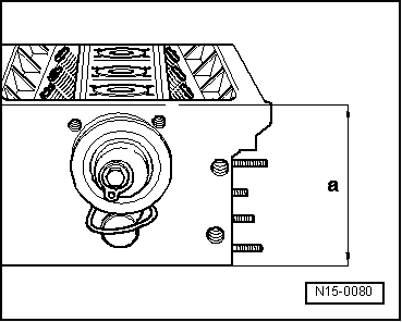
→ Fig. 2     Reworking cylinder head sealing surface

Cylinder head reworking dimension:
     a = At least 108.25 mm

 
N15-0087

→ Fig. 3     Checking camshaft axial clearance

Special tools, workshop equipment, testers, measuring instruments and auxiliary items required

  • ◆ VW 387 Universal dial gauge bracket
  • ◆ Dial gauge

Perform measurements with camshaft housing removed and sealing cover fitted.

Wear limit: max. 0.40 mm

 
N15-0376

→ Fig.4     Camshaft identification, valve timing

Identification between cam pairs

Engine codes

AHW, AUA
APE

AFK, AUB
AQQ

Cyl. 1 + 2

Cyl. 1 + 2

Inlet shaft -E-

"036AC"

"036AF"

Exhaust shaft -A-

"036AA"

"036AG"

Valve timing at 1 mm valve lift

Engine codes

AHW, AUA
APE

AFK, AUB
AQQ

Inlet opens ATDC

19.1 °

15.5 °

Inlet closes ABDC

15.1 °

29.5 °

Exhaust opens BBDC

20.2 °

24.0 °

Exhaust closes BTDC

15.3 °

10.0 °

 
V15-0024

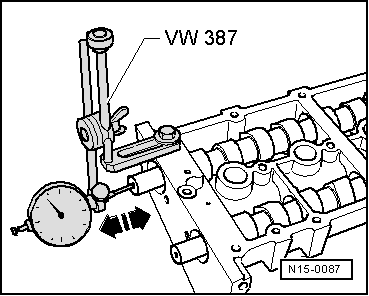
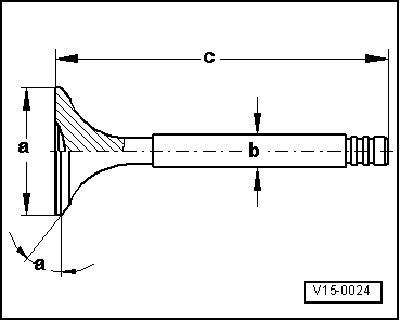
→ Fig. 5     Valve dimensions

Note:

Valves must not be reworked. Only lapping-in is permitted.

Dimension

Inlet valve

Exhaust valve

øa

mm

29.5

26.0

øb

mm

5.973

5.953

c

mm

100.9

100.5

α

45

45

Reworking valve seats > < Removing and installing camshaft housing