volkswagen Workshop Repair Guides

Volkswagen Workshop Service and Repair Manuals

Securing engine to assembly stand > < Removing and installing engine
4-cyl. injection engine (4-valve, roller rocker finger), Mechanics
Removing and installing engine
Notes on removing

Note:

Check whether a coded radio is installed as during the forthcoming work sequences the battery earth strap must be disconnected. Obtain radio code first if necessary.

  • ‒ The engine is removed forwards together with the gearbox.
  • ‒ All cable ties which are opened or cut open when removing engine, must be replaced in the same position when installing engine.
 
N13-0592
  • ‒ → Remove cover above camshaft housing -arrows-.
  • ‒ Remove air cleaner:

=> Repair group 24; Servicing injection; Dismantling and assembling air cleaner

  • ‒ Remove battery
  • ‒ Remove battery tray.
  • ‒ Unclip cable guide -from battery to bulkhead-.
  • ‒ Release plus wire from battery to starter motor (is removed together with assembly).
 
N13-0597
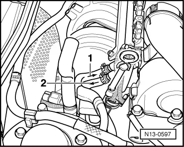
  • ‒ → Disconnect fuel supply and fuel return pipes at fuel rail, items -1- and -2-.
Warning!
Fuel supply lines are under pressure! Before removing from hose connection wrap a cloth around the connection. Then release pressure by carefully pulling hose off connection.
  • ‒ Seal the pipes so that the fuel system is not contaminated by dirt etc.
  • ‒ Observe rules for cleanliness .
  • ‒ Disconnect clutch cable:

=> 5-speed manual gearbox 085; Repair group 30; Servicing clutch mechanism

  • ‒ Remove connecting hose for air cleaner/air intake connecting piece.
  • ‒ Open and close the expansion tank sealing cap to release pressure in cooling system.
  • ‒ Loosen or separate the following components:
    • ‒ The hose from activated charcoal filter system to throttle valve control part
    • ‒ The vacuum hose from brake servo to inlet manifold
    • ‒ The collective connectors below thermostat housing
    • ‒ The connector from engine speed sender below oil dipstick tube bracket, and pull connector out from retainer
    • ‒ The connector from ignition transformer, from Hall sender and throttle valve control part
    • ‒ The connector from coolant temperature sender, oil pressure switch and the engine oil temperature switch
  • ‒ Remove noise insulation tray:

=> General body repairs; Repair group 50; Front body; Removing insulation tray

  • ‒ Loosen or separate the following components:
    • ‒ Connector for Lambda probes
  • ‒ Drain coolant => Page 19-11 .
  • ‒ Pull off coolant hose at engine with assembly tool for spring-type clamps VAS 5024.
  • ‒ Loosen belt pulley securing bolts from power steering vane pump.
  • ‒ Remove ribbed belt => Page 13-12 .
  • ‒ Unbolt power steering vane pump and secure to sub-frame with wire; hoses remain connected:

=> Running gear; Repair group 48; Assembly overview: vane pump, reservoir, hydraulic lines; Removing and installing power steering vane pump.

  • ‒ Remove left and right-hand drive shaft on gearbox and tie up:

=> Running gear, Axles, Steering; Repair group 40; Servicing front suspension; Removing and installing drive shafts

Vehicles with air conditioner

  • ‒ Removing air conditioner compressor:
  • ‒ Observe additional information and removal instructions =>Page10-15
 
N10-0100
  • ‒ → Unbolt pendulum support from gearbox.
  • ‒ Separate front exhaust pipe from exhaust manifold => Page 26-2 , exhaust manifold, front exhaust pipe and catalyst with attachments.
  • ‒ Disconnect cable selector mechanism from gearbox.

=> 5-speed manual gearbox 085; Repair group 34; Servicing selector mechanism (cable selector mechanism); Removing and installing selector mechanism

  • ‒ Pull vacuum and breather hoses off engine.
  • ‒ Disconnect all electric wires from gearbox, alternator and starter and move clear.
  • ‒ Remove securing clamps for power steering pressure pipe.
  • ‒ Removing lock carrier with attachments:

=> General body repairs, Exterior; Repair group 50; Body, front; Removing and installing lock carrier with attachments.

 
N10-0182
  • ‒ → Attach lifting tackle 2024 A as follows and lift slightly with workshop crane:

     Pulley end:
     3rd hole in hook at position 1

     Flywheel end:
     3rd hole in hook at position 5

Warning!
The hooks and locating pins must be secured with locking pins.

Notes:

  • ◆ The positions marked 1...4 on the bar must be towards the pulley end.
  • ◆ The holes in the hook rails are counted up from the hook.
  • ‒ Remove power steering reservoir and tie up.
 
N10-0194
  • ‒ → Unbolt assembly at gearbox and engine mountings.
  • ‒ Lower assembly until it is released from the gearbox mounting.

Turn assembly slightly to left (engine forwards, gearbox rearwards) and lift engine carefully out forwards.

Note:

When the assembly is lifted off, it must be carefully guided to prevent damage to the bodywork.

Securing engine to assembly stand > < Removing and installing engine