volkswagen Workshop Repair Guides

Volkswagen Workshop Service and Repair Manuals

Dismantling and assembling pistons and conrods > < Renewing crankshaft oil seal -belt pulley end-
4-cyl. injection engine (4-valve, roller rocker finger), Mechanics
Dismantling and assembling cylinder block, crankshaft and flywheel
Renewing crankshaft sealing flange -flywheel end-
 
W13-0098

Special tools, workshop equipment, test and measuring appliances and auxiliary items required

  • ◆ T10017 Assembly device
  • ◆ V.A.G 1331 Torque wrench (5...50 Nm)
  • ◆ V.A.G 1332/11 Open ring spanner
  • ◆ Hexagon bolts (Qty. 3)
    M6 x 35 mm
  • ◆ Feeler gauge
  • ◆ Vernier gauge

Pressing out sealing flange with sender wheel

Notes:

  • ◆ To enable the work sequence to be shown more clearly the sequence is described as for engine removed.
  • ◆ The work sequence is the same when the engine is in the vehicle and the gearbox removed.

Work sequence

  • ‒ Remove pressure plate.
  • ‒ Remove flywheel.
  • ‒ Remove the intermediate plate.
 
N13-0380
  • ‒ Set engine to TDC No. 1 cylinder , Checking valve timing.
  • ‒ Remove oil sump .
  • ‒ → Remove engine speed sender -arrow-.
  • ‒ Undo sealing flange securing bolts.

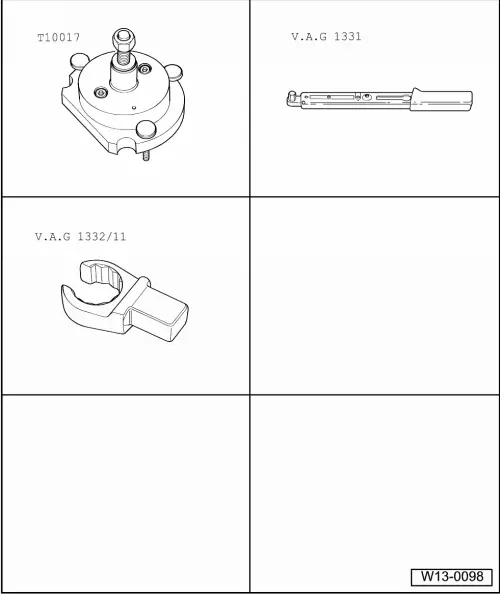
Note:

Sealing flange and sender wheel are pressed off the crankshaft together with Qty. 3 M6 x 35 mm bolts.

 
N13-0381
  • ‒ → Screw Qty. 3 M6 x 35 mm bolts into the threaded holes -arrows- of the sealing flange.
  • ‒ Screw the bolts alternately (a 1/2 turn(180°) for each bolt) into the sealing flange and press the sealing flange along with the sender wheel off the crankshaft.

Pressing in sealing flange with sender wheel

Notes:

  • ◆ Gradual introduction of a new generation of sealing flanges with PTFE seal (Teflon). The sealing flange with spring ring will continue to be offered as spare part.
    When fitting a new sealing flange, be careful to use the same type of sealing flange that was previously fitted.
  • ◆ The sealing flange with a PTFE sealing ring is equipped with a sealing lip support ring. This support ring serves the function of a fitting sleeve and may not be removed prior to installation.
  • ◆ Sealing flange and sender wheel must not be separated or twisted after removal from packaging.
  • ◆ The sender wheel of a sealing flange with spring ring has an Elastomer coating on the sealing surface to crankshaft. This coating must never come into contact with dirt or grease.
  • ◆ The sender wheel is held in its installation position by a fixture on the assembly device T10017 locating pin.
  • ◆ Sealing flange and seal are one unit and must be replaced together with the sender wheel only.
 
N13-0388
  • ◆ The assembly appliance T10017 maintains its installation position to the crankshaft via a guide pin which is inserted into a threaded hole in the pressure plate/drive plate.

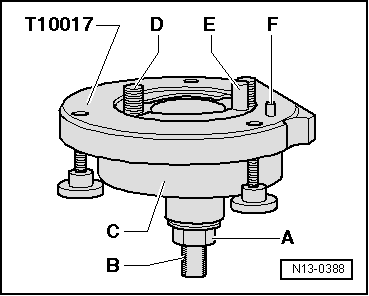
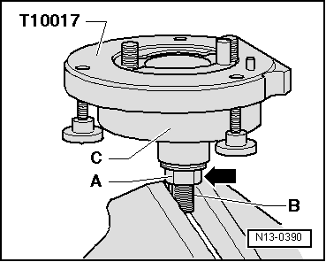
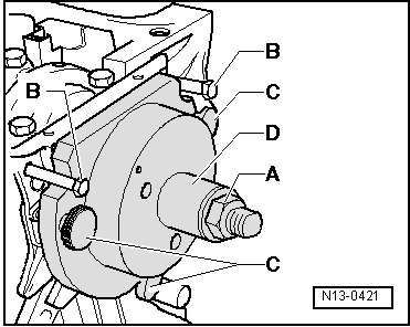
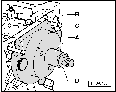
→ A - Hexagon nut

B - Clamping surface (ground section of spindle)

C - Tool bell housing

D - Socket head bolt

E - Guide pin

 
N13-0388

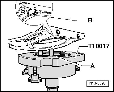
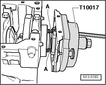
F - Locating pin

A-Assembling sealing flange with sender wheel on assembly appliance T10017

  • ‒ → Screw hexagon nut -A- to shortly before the clamping surface (ground section) -B- on the threaded spindle.
 
N13-0390
  • ‒ → Clamp assembly appliance T10017 in a vice on clamping surface (ground section) on threaded spindle.
  • ‒ Press assembly bell housing -C- downwards so that it lies on the hexagon nut -A- -arrow-.

Note:

Inner part of assembly appliance and assembly bell housing must be at same height (level).

 
N13-0391
  • ‒ → Remove securing clip -A- on new sealing flange.

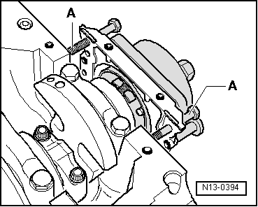
Note:

The sender wheel must not be taken out of the sealing flange or twisted.

 
N13-0383

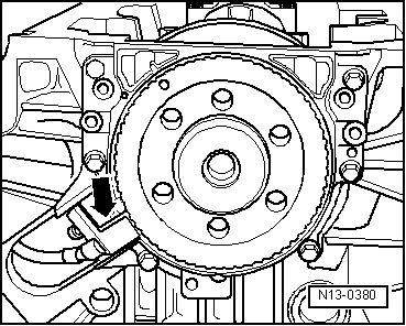
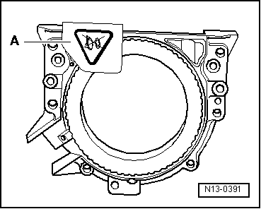
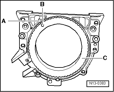
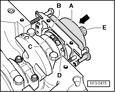
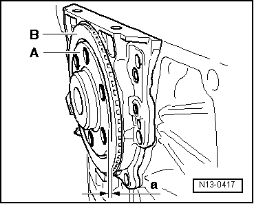
→ The locating hole -B- on the sender wheel -C- must align with the marking -A- on the sealing flange.

 
N13-0386
  • ‒ → Place the sealing flange (with the forward side downwards) on a clean flat surface.
  • ‒ Push the sender wheel (sealing lip support ring for PTFE sealing ring) -A- downwards in direction of arrow until it lies on the flat surface.
 
N13-0384

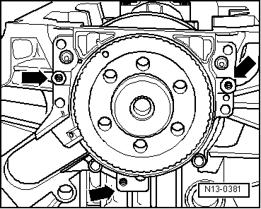
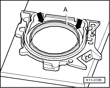
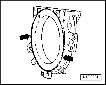
→ The upper edge of the sender wheel and the forward edge of the sealing flange must align -arrows-.

 
N13-0392
  • ‒ → Place the sealing flange, with the forward side on the assembly appliance T10017, so that the locating pin -A- can be inserted in the sender wheel hole -B-.

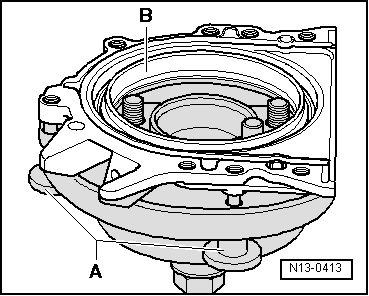
Note:

Ensure the sealing flange lies flat on the assembly appliance.

 
N13-0413
  • ‒ → Push the sender wheel -B- (Sealing lip support ring for PTFE sealing ring) onto the surface of the assembly appliance whilst tightening the three knurled screws -A-, so that the locating pin cannot slide out of sender wheel hole.

Note:

Ensure the sender wheel remains fixed on the assembly appliance when installing the sealing flange.

B-Assembling appliance T10017 with sealing flange on crankshaft flange

Prerequisites

 
N13-0414
  • ● Crankshaft flange must be free of oil and grease.
  • ● Engine positioned at TDC No. 1 cylinder.

Work sequence

  • ‒ → Unscrew hexagon nut -A- to end of threaded spindle.
  • ‒ Press assembly appliance threaded spindle in direction of arrow, until the hexagon nut -A- lies against the assembly bell housing -C-.
 
N13-0393
  • ‒ Align flat side of assembly bell housing towards oil sump side of crankcase sealing surface.
  • ‒ → Secure assembly appliance to crankshaft flange with hexagon socket head bolts -A-

Note:

Screw hexagon socket head bolts -A- into crankshaft flange (approx. 5 threads).

 
N13-0394
  • ‒ → Screw two M6 x 35 mm bolts -A- into cylinder block to guide sealing flange.

C-Fitting assembly appliance T10017 onto crankshaft flange

 
N13-0415
  • ‒ → Slide assembly bell housing -A- in direction of arrow by hand until the sender wheel - B- (Sealing lip support ring for PTFE sealing ring) lies against the crankshaft flange -C-.

Note:

The assembly appliance guide pin -D- is guided into threaded hole in crankshaft during the fitting sequence. This ensures the sender wheel reaches its final installation position.

  • ‒ Hold assembly bell housing in this position and screw both assembly appliance hexagon socket head bolts hand tight.
  • ‒ Screw hexagon nut -E- onto threaded spindle by hand until it lies against the assembly bell housing -A-.
 
N13-0617

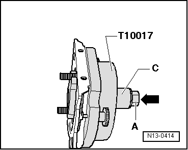
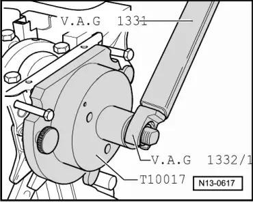
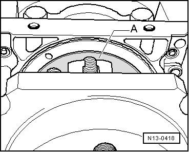
D-Pressing sender wheel onto crankshaft flange with assembly appliance T10017

  • ‒ → Tighten assembly appliance hexagon nut using torque wrench V.A.G 1331 and open ring spanner V.A.G 1332/11.
         Tightening torque: 35 Nm

Note:

A small air gap must be present between cylinder block and sealing flange after tightening hexagon nut to 35 Nm.
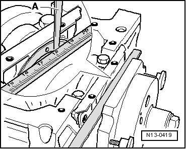
 
N13-0421

E-Checking sender wheel installation position on crankshaft

  • ‒ → Screw hexagon nut -A- to end of threaded spindle.
  • ‒ Remove the two M6 x 35 mm hexagon bolts -B- from cylinder block.
  • ‒ Screw the three thumb wheels -C- out of sealing flange.
  • ‒ Pull assembly appliance assembly bell housing -D- back to hexagon nut -A- (Only for sealing flange with spring ring).
 
N13-0417

→ The sender wheel has the correct installation position on crankshaft when a gap of
     -a- = 0.5 mm
exists between crankshaft flange -A- and sender wheel -B-.

Note:

If the sealing flange has a PTFE sealing ring, completely unbolt the assembly appliance T10017 and remove the sealing lip support ring.

To enable the measurements to be shown more clearly the crankshaft flange is illustrated without the fitted assembly appliance T10017.

 
N13-0418
  • ‒ → Place a vernier caliper against the crankshaft flange -A- (hatched area).
 
N13-0419
  • ‒ → Measure the distance -a- between vernier caliper and sender wheel with a feeler gauge -A-.

Is measurement -a- too small:

  • ‒ Re-press sender wheel .

When dimension -a- is achieved:

  • ‒ Remove assembly appliance.
  • ‒ Tighten the new securing bolts for the sealing flange using alternate and diagonal sequence.
         Tightening torque: 10 Nm
 
N13-0380
  • ‒ → Install engine speed sender -arrow-.
         Tightening torque: 5 Nm
  • ‒ Install sump .
  • ‒ Install intermediate plate.
  • ‒ Install flywheel/drive plate with new bolts.
 
N13-0420

F-Re-pressing sender wheel

  • ‒ → Slide assembly bell housing -A- to sealing flange -B- by hand.
  • ‒ Screw two M6 x 35 mm bolts -C- into cylinder block to guide sealing flange -B-.
  • ‒ Screw hexagon nut -D- along threaded spindle, by hand, until it contacts the assembly bell housing -A-.
 
N13-0617
  • ‒ → Tighten assembly appliance hexagon nut using torque wrench V.A.G 1331 and open ring spanner V.A.G 1332/11.
         Tightening torque: 40 Nm
  • ‒ Check installation position of sender wheel on crankshaft again => Page 13-31 .

If dimension -a- is too small again:

  • ‒ Tighten hexagon nut to
         45 Nm.
  • ‒ Check installation position of sender wheel on crankshaft again => Page 13-31 .

Dismantling and assembling pistons and conrods > < Renewing crankshaft oil seal -belt pulley end-