volkswagen Workshop Repair Guides

Volkswagen Workshop Service and Repair Manuals

Safety precautions when working on the fuel supply system > < Removing and installing parts of fuel supply system
4-cyl. injection engine (4-valve, roller rocker finger), Mechanics
Removing and installing parts of fuel supply system
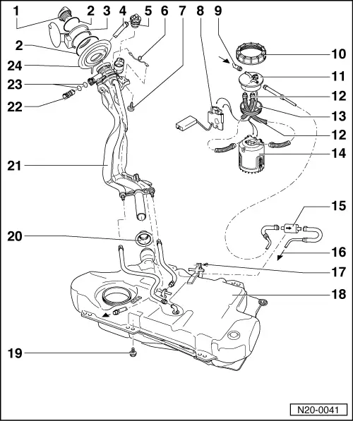
Removing and installing fuel tank with its attachments and fuel filter
 
N20-0041
  • Cap
  • Retaining ring
  • Tank flap unit
    • ◆ Removing and installing

=> General body repairs; Repair group 55; fuel flap unit

  • Vent pipe
    • ◆ To activated charcoal filter
      , item 5
  • Gravity/overflow valve
    • ◆ To remove, release locking lug and unclip valve upwards out of filler neck
    • ◆ Check valve for through-flow
      valve vertical: open,
      valve tilted 90 °: closed
 
N20-0041
  • Earth connection
  • 4 Nm
  • Fuel gauge sender
    • ◆ Adjusting:

=> Current flow diagrams, Electrical fault finding and Fitting locations

  • Return hose/line
    • ◆ Blue or with blue marking
    • ◆ From fuel manifold

=> Repair group 24; mixture preparation, injection

  • Union nut, 75 Nm
    • ◆ Remove and install with 3217
  • Flange
    • ◆ Note installation position on fuel tank => Fig. 1
  • Corrugated tube
    • ◆ Must not contact fuel tank, otherwise pump noises will be transferred
 
N20-0041
  • Sealing ring
    • ◆ Coat with fuel when installing
    • ◆ Renew if damaged
  • Fuel delivery unit
    • ◆ Removing and installing
    • ◆ Checking fuel pump
      => Page 20-17

Note:

After completing work on fuel delivery unit or fuel gauge sender ensure that the corrugated tubing between delivery unit and flange does not contact the fuel tank (transfer of pump noises).

  • Fuel filter
    • ◆ Fitting position: Arrow points in direction of flow
 
N20-0041
  • Supply pipe
    • ◆ Black
    • ◆ To fuel manifold

=> Repair group 24; mixture preparation, injection

  • 3 Nm
  • Fuel tank
    • ◆ Removing and installing
      => Page 20-15
    • ◆ Press clamping washer from heat shield tightly onto pins on vehicle floor
  • 25 Nm
  • Sealing boot
    • ◆ After installing filler pipes fit over fuel tank connections, having turned boot inside out
  • Filler pipes
    • ◆ With non-return valve
 
N20-0041
  • Vent valve
    • ◆ Checking =>Fig.
    • ◆ To remove pull locking latch lightly to inside -arrow- and pull valve out
  • O-ring
    • ◆ Renew if damaged
  • Cup
    • ◆ For filler pipes
 
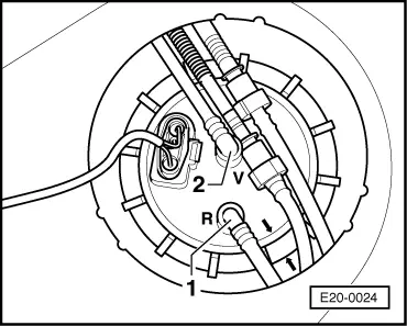
E20-0024

→ Fig. 1     Installation position of fuel delivery unit flange

Marking on the flange must align with marking on the fuel tank.

Blue or blue marked return pipe -1- to connection with identification -R-.

Black supply pipe -2- to connection with identification -V-.

Note:

After installing fuel delivery unit flange, check that the supply, return and breather pipes are still clipped onto the fuel tank.

 
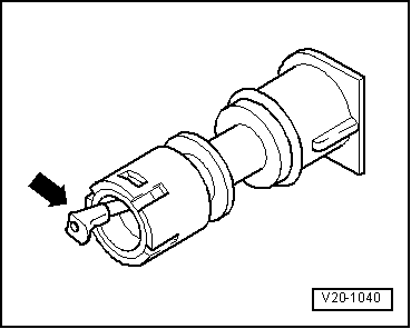
V20-1040

→ Fig. 2     Checking vent valve

Lever in rest position: Closed

Lever pushed in direction of arrow: Open

Note:

Before installing vent valve remove fuel tank cap.

Safety precautions when working on the fuel supply system > < Removing and installing parts of fuel supply system