Polo Mk3
|
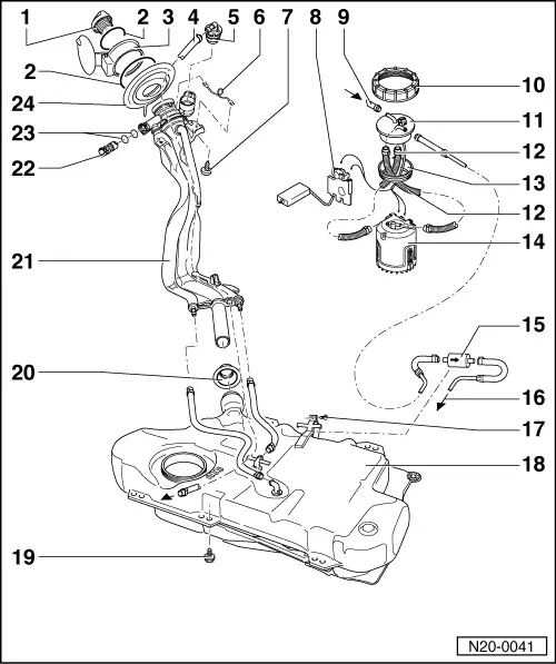
Removing and installing parts of fuel supply system
Removing and installing fuel tank with its attachments
|
 |
|
=> General body repairs; Repair group 55; fuel flap unit
|
|
|
=> Current flow diagrams, Electrical fault finding and Fitting locations
=> Repair group 24; mixture preparation, injection
|
|
|
Note: After completing work on fuel delivery unit or fuel gauge sender ensure that the corrugated tubing between delivery unit and flange does not contact the fuel tank (transfer of pump noises).
|
|
|
=> Repair group 24; mixture preparation, injection
|
|
|
|
 |
|
|
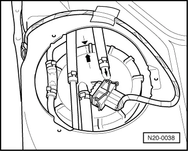
→ Fig. 1 Fitting position of fuel delivery unit flange Marking on the flange must align with marking on the fuel tank. |
 |
|
|
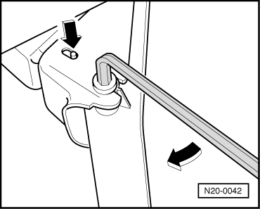
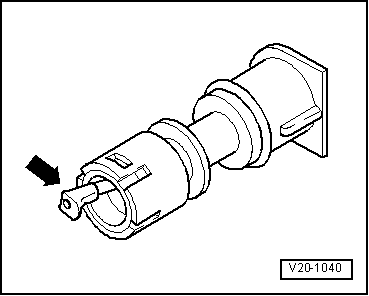
→ Fig. 2 Checking vent valve Lever in rest position: Closed Lever pushed in direction of arrow: Open |