
Checking Injectors for Polo Mk3 4AV Injection and Ignition System
 |
|
Check conditions
|
 |
|
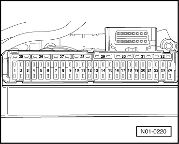
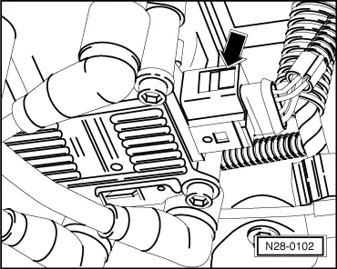
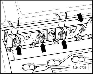
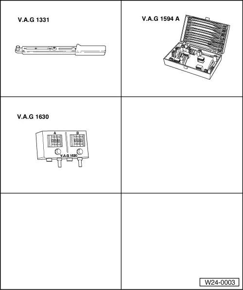
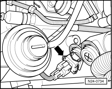
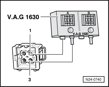
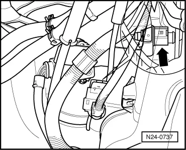
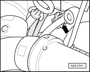
Test sequence
|
 |
|
|
 |
|
|
 |
|
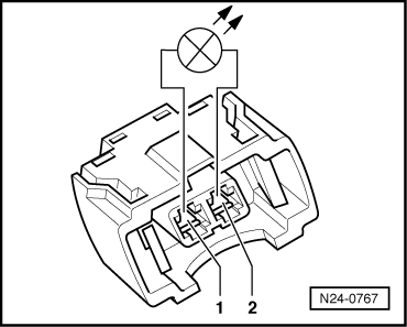
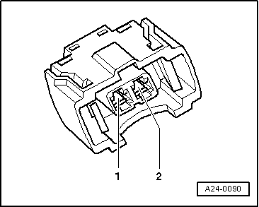
If the LED does not light up on any cylinder: |
 |
|
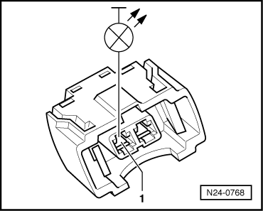
If the LED does not light up:
If the LED lights up on one or several cylinders: |
 |
|
|
 |
|
|
 |
|
|
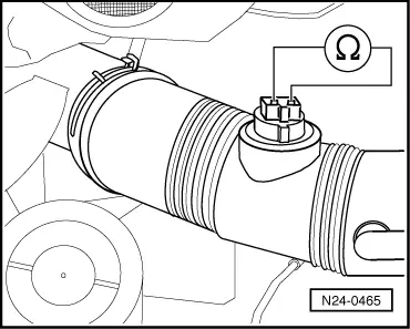
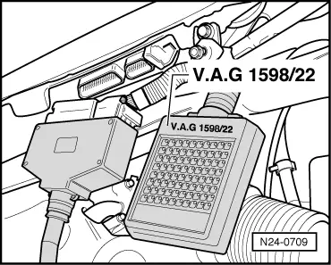
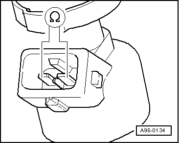
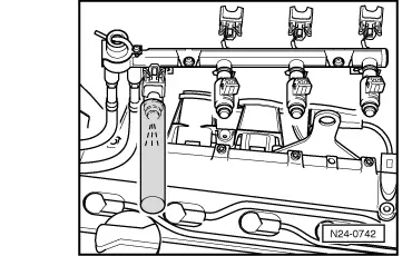
Checking resistance of injectors Test sequence
When the engine is warm the resistance will be approx. 4...6 ωhigher. If the specification is not attained: |
|
|
|
Test conditions
Test sequence |
 |
|
|
 |
|
|
 |
|
|
 |
|
 |
|
If the fuel loss is greater: Perform installation of injectors in reverse order. When doing this note the following:
|