volkswagen Workshop Repair Guides

Volkswagen Workshop Service and Repair Manuals

Checking data bus > < Checking rpm signal
4CV fuel injection and ignition system
Checking additional signals
Checking gearbox intervention signal when a gear is shifted

Notes:

  • ◆ This signal is produced by the automatic gearbox control unit during a gearshift. The signal enables the ignition timing to be briefly retarded by varying amounts (torque reduction) depending on the engine load and engine speed. This smooths out the slight jerk as the gear engages.
  • ◆ The signal is a square wave signal which is fed to contact 23 on the engine control unit.
  • ◆ Because the signal is very brief the V.A.G. 1551 does not always recognise the command to retard the ignition timing.

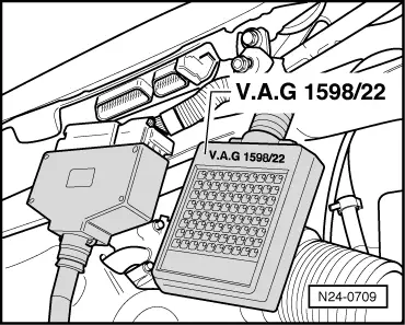
Special tools, workshop equipment, testers, measuring instruments and auxiliary items required

  • ◆ Fault reader V.A.G 1551 or vehicle system tester V.A.G 1552 with cable V.A.G 1551/3A
  • ◆ Test box V.A.G 1598/22
  • ◆ Adapter set V.A.G 1594
  • ◆ Hand multimeter V.A.G 1526 or multimeter V.A.G 1715
  • ◆ Current flow diagram

Test conditions

  • ● No faults must be stored in fault memory , interrogating and erasing fault memory.

Test sequence

Note:

To check the gearbox intervention signal the vehicle must be driven. To do this a second person is necessary.

Warning!
Secure fault reader to rear seat and operate from this position.

Observe the valid safety precautions when carrying out a road test => Page 24-28 .

  • ‒ Connect fault reader V.A.G 1551 (V.A.G 1552). Start engine and select "Address word" 01 of engine control unit. When doing this the engine must be running at idling speed.
    (Connecting fault reader and selecting engine control unit => Page 01-5 .)
 
→ Indicated on display:
Rapid data transfer     HELP
Select function XX
  • ‒ Press keys 0 and 8 for the function "Read measured value block" and confirm entry with Q key.
 
→ Indicated on display:
Read measured value block     HELP
Input display group number XXX
  • ‒ Press keys 0, 0 and 1 for "Display group number 1" and confirm entry with Q key.
 
→ Indicated on display:
(1...4 = Display zones)
Read measured value block     1     ⇒
     1     2     3     4
  • ‒ Carry out test drive with a 2nd person to observe display.
  • ‒ Observe -8 digit number block- in display zone 4 :
  • 2nd position from left displays 0
         Display: 00000000 = No gearbox intervention
  • 2nd position from left displays 1
         Display: 01000000 = Gearbox intervention

Note:

When the gearbox control unit gives the command for the ignition timing to be retarded the readout will change briefly from "0" to "1".

  • ‒ Press the ⇒key.
  • ‒ Press keys 0 and 6 for the "End output" function and confirm input with the Q key.
  • ‒ Switch off ignition.

If the torque reduction is not displayed in measured value block during a gear shift or the fault code 00545 (in automatic gearbox control unit) is displayed:

 
N24-0709
  • ‒ → Connect test box V.A.G 1598/22 to control unit wiring harness.
  • ‒ Check the wiring from contact 23 on engine control unit to automatic gearbox control unit for open/short circuit:

=> Current flow diagrams, Electrical fault finding and Fitting locations

Checking data bus > < Checking rpm signal