volkswagen Workshop Repair Guides

Volkswagen Workshop Service and Repair Manuals

Checking coolant temperature sender > < Checking intake manifold pressure sender
4CV fuel injection and ignition system
Checking components
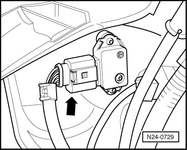
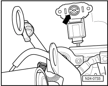
Checking intake air temperature sender

Note:

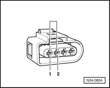
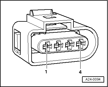
Only gold-plated contacts may be used when servicing the sender connector contacts

Special tools, workshop equipment, testers, measuring instruments and auxiliary items required

  • ◆ Fault reader V.A.G 1551 or vehicle system tester V.A.G 1552 with cable V.A.G 1551/3A
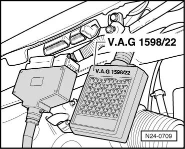
  • ◆ Test box V.A.G 1598/22
  • ◆ Hand multimeter V.A.G 1526 or multimeter V.A.G 1715
  • ◆ Adapter set V.A.G 1594
  • ◆ Current flow diagram
  • ◆ Chilling spray (commercially available)

Test sequence

  • ‒ Connect the fault reader V.A.G 1551 (V.A.G 1552). Then switch ignition on and select engine control unit with the "Address word" 01.
    (Connecting fault reader and selecting engine control unit .)
 
→ Indicated on display:
Rapid data transfer     HELP
Select function XX
  • ‒ Press keys 0 and 8 for the function "Read measured value block" and confirm entry with Q key.
 
→ Indicated on display:
Read measured value block     HELP
Input display group number XXX
  • ‒ Press keys 0, 0 and 2 for "Display group number 2" and confirm entry with Q key.
 
→ Indicated on display:
(1...4 = Display zones)
Read measured value block 2     ⇒
     1     2     3     4
  • ‒ Read off intake air temperature value in display zone 4.

Display

Cause

Continuation of check

-40 °C

Open circuit or short to positive

=> Page 24-59

120 °C

Short to earth

=> Page 24-61

Approx. ambient temperature1)

---

=> Page 24-63

     1)     If a temperature is displayed which is below the ambient air temperature of the sender, check sender wiring for transfer resistances. Note when doing this that sender is heated from external sources, e.g. radiated heat when engine is not running.

Continuation of check when display -40 °C:

 
N24-0729
  • ‒ → Pull 4 pin connector off intake air temperature sender (G42) with intake manifold pressure sender (G71) -arrow-.
 
N24-0804
  • ‒ → Bridge connector contacts 1+2 using aux. cables from V.A.G 1594 and observe display.

If the display jumps to 120 °C:

  • ‒ Press ⇒key.
  • ‒ Press keys 0 and 6 for the function "End output" and confirm entry with the Q key.
  • ‒ Switch off ignition.
  • ‒ Renew the intake manifold pressure sender (G71) with intake air temperature sender (G42)
    => Page 24-20 , item 11 .

If the display remains at -40 °C:

 
N24-0709
  • ‒ Press ⇒key.
  • ‒ Press keys 0 and 6 for the function "End output" and confirm entry with the Q key.
  • ‒ Switch off ignition.
  • ‒ → Connect test box V.A.G 1598/22 to control unit wiring harness.
 
A24-0094
  • ‒ → Check the wiring between test box and 4 pin connector -1- for open circuit using current flow diagram.
         Contact 1+socket 67
         Contact 2+socket 54
         Wire resistance: Max. 1.5 ω
  • ‒ Check wiring additionally for short circuit to battery positive.
         Specification: ∞ω

If no wiring fault is detected:

  • ‒ Renew the intake manifold pressure sender (G71) with intake air temperature sender (G42)
    => Page 24-20 , item 11 .

Continuation of check when display shows 120 °C:

 
N24-0729
  • ‒ → Pull 4 pin connector off intake air temperature sender (G42) with intake manifold pressure sender (G71) -arrow-.

If the display jumps to -40 °C:

  • ‒ Press ⇒key.
  • ‒ Press keys 0 and 6 for the function "End output" and confirm entry with the Q key.
  • ‒ Switch off ignition.
  • ‒ Renew the intake manifold pressure sender (G71) with intake air temperature sender (G42)
    => Page 24-20 , item 11 .
 
N24-0709

If the display remains at 120 °C:

  • ‒ Press ⇒key.
  • ‒ Press keys 0 and 6 for the function "End output" and confirm entry with the Q key.
  • ‒ Switch off ignition.
  • ‒ → Connect test box V.A.G 1598/22 to control unit wiring harness.
 
A24-0094
  • ‒ → Check the wiring between test box and 4 pin connector -1- for open circuit using current flow diagram.
         Contact 1+socket 67
         Contact 2+socket 54
         Wire resistance: Max. 1.5ω
  • ‒ Check wiring additionally for short circuit to battery positive.
         Specification: ∞ω

If no wiring fault is detected:

  • ‒ Renew the intake manifold pressure sender (G71) with intake air temperature sender (G42)
    => Page 24-20 , item 11 .

Continuation of check when display = ambient temperature:

 
N24-0733

Functional check of sender

  • ‒ Remove air cleaner => Page 24-27 , Fig. 3 .
  • ‒ → Remove intake air temperature sender together with intake manifold pressure sender (connector remains connected).
  • ‒ Note intake air temperature value in display zone 4.
  • ‒ Spray sender with commercial chilling agent whilst observing the temperature value. The temperature value must
         decrease.
  • ‒ Press ⇒key.
  • ‒ Press keys 0 and 6 for the function "End output" and confirm entry with the Q key.
  • ‒ Switch off ignition.

If the specification is not obtained:

  • ‒ Renew the intake manifold pressure sender (G71) with intake air temperature sender (G42)
    => Page 24-20 , item 11 .

Checking coolant temperature sender > < Checking intake manifold pressure sender