volkswagen Workshop Repair Guides

Volkswagen Workshop Service and Repair Manuals

Replacing engine control unit > < Engine control unit
4CV fuel injection and ignition system
Engine control unit
Checking control unit voltage supply

Special tools, workshop equipment, testers, measuring instruments and auxiliary items required

  • ◆ Fault reader V.A.G 1551 or vehicle system tester V.A.G 1552 with cable V.A.G 1551/3A
  • ◆ Test box V.A.G 1598/22
  • ◆ Hand multimeter V.A.G 1526 or multimeter V.A.G 1715
  • ◆ Adapter set V.A.G 1594
  • ◆ Current flow diagram
 
N24-0831

Check conditions

  • ● → Fuses No. 32 and 37 must be OK.
  • ● Earth connection in plenum chamber OK.
  • ● The battery voltage must be at least 11.5 V.
  • ● If the vehicle is equipped with an air conditioner, this must be switched off.
  • ● All electrical consumers, e.g. lights and rear window heating must be switched off.
  • ● On vehicles with automatic gearbox the selector lever must be in "P" or "N" position.
  • ● Alternator OK, checking:

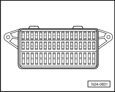
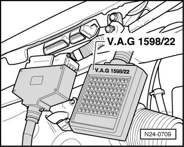
=> Current flow diagrams, Electrical fault finding and Fitting locations

Test sequence

  • ‒ Connect fault reader V.A.G 1551 (V.A.G 1552). Start engine and select "Address word" 01 of engine control unit. When doing this the engine must be running at idling speed.
    (Connecting fault reader and selecting engine control unit .)
 
→ Indicated on display:
Rapid data transfer     HELP
Select function XX
  • ‒ Press keys 0 and 8 for the function "Read measured value block" and confirm entry with Q key.
 
→ Indicated on display:
Read measured value block     HELP
Input display group number XXX
  • ‒ Press keys 0, 0 and 2 for "Display group number 2" and confirm entry with Q key.
 
→ Indicated on display:
(1...4 = Display zones)
Read measured value block 2     ⇒
     1     2     3     4
  • ‒ Read off figure displayed in display zone 3.
         Specification: At least 11.5 V
  • ‒ Press the ⇒key.
  • ‒ Press keys 0 and 6 for the "End output" function and confirm input with the Q key.
  • ‒ Switch off ignition.

If the specification is not attained:

 
N24-0709
  • ‒ → Connect test box V.A.G 1598/22 to control unit wiring harness.

Checking voltage supply terminal 30

  • ‒ Measure supply voltage between test box sockets 1+2 using multimeter and adapter cables from V.A.G 1594:
         Specification: at least 11.5 V

If the specification is not attained:

  • ‒ Check wiring connections to relay plate according to current flow diagram.

=> Current flow diagrams, Electrical fault finding and Fitting locations

Checking voltage supply terminal 15

  • ‒ Measure supply voltage between test box sockets 2+3 using multimeter and adapter cables from V.A.G 1594.
  • ‒ Switch on ignition.
         Specification: min. 11.5 V

If the specification is not attained:

  • ‒ Check wiring connections to relay plate according to current flow diagram.

=> Current flow diagrams, Electrical fault finding and Fitting locations

Replacing engine control unit > < Engine control unit