|
→
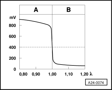
Lambda probe voltage Ufont=symbol charset=fontspecific code=108 TeX='\lambda ' descr='[lambda]' in mV
A: High Lambda probe voltage
-
◆ Rich mixture (excess of fuel or shortage of air)
-
◆ Higher CO value
B: Low Lambda probe voltage
-
◆ Lean mixture (shortage of fuel or excess air)
-
◆ Lower CO value
Evaluating display group 1, display zone 3 - Lambda probe voltage
|
Appears on display
|
Possible fault cause
|
Fault elimination
|
|
Display does not fluctuate
|
- Large amount of unmetered air
|
- Check air intake system for leaks
|
|
(Constant 0.000...
0.300 V
or
|
- Spark plug defective
|
- Check spark plugs
|
|
Constant 0.700...1.000 V)
Cont. on next page
|
- Fuel pressure too low or too high
|
- Check fuel pressure regulator and holding pressure => Page 24-84
|
|
Appears on display
|
Possible fault cause
|
Fault elimination
|
|
Continued
|
- Injector defective
|
- Check injectors => Page 24-74
|
|
|
- Coolant temperature sender defective
|
- Check coolant temperature sender
|
|
|
- Activated charcoal filter solenoid valve 1
|
- Check solenoid valve 1
, final control diagnosis
|
|
|
- Lambda probe heating not functioning
|
- Check Lambda probe heating
=> Page 24-32
|
|
|
- Lambda probe(s) defective or soiled
|
- Check Lambda probe and Lambda control => Page 24-92
|
|
Constant 1.200 V
|
- Short to positive via:
- Lambda probe, probe wire, earth wire, engine control unit
|
- Check Lambda probe wiring
=> Page 24-92
, checking Lambda probe and Lambda control
|
|
Constant between
0.040...0.050 V
|
- Open circuit in:
- Lambda probe, probe wire, earth wire, engine control unit
|
|
|
Constant 0.000 V
|
- Short to earth via:
- Lambda probe, probe wire, earth wire, engine control unit
|
|
Significance of figures in 8 digit number block, display zone 4 - Adjustment conditions
|
X
|
X
|
X
|
X
|
X
|
X
|
X
|
X
|
Signifies
|
|
|
|
|
|
|
|
|
|
Coolant temperature
0 = Coolant temperature above 80 °C
1 = Coolant temperature below 80 °C
|
|
|
|
|
|
|
|
|
Engine speed
0 = Engine speed below 1800 rpm
1 = Engine speed above 1800 rpm
|
|
|
|
|
|
|
|
Throttle valve
0 = Throttle valve closed
1 = Throttle valve open
|
|
|
|
|
|
|
Lambda control
0 = Lambda control OK.
1 = Fault in the Lambda control
|
|
|
|
|
|
Idling switch (F60)
0 = Idling switch closed
1 = Idling switch open
|
|
|
|
|
Air conditioner compressor
0 = Air conditioner compressor switched off
1 = Air conditioner compressor switched on
|
|
|
|
Gearbox intervention during gear shift
0 = No intervention
1 = Intervention
|
|
|
Fault memory
0 = No fault stored in fault memory
1 = Fault stored in fault memory
|
Note on 2nd position in 8 digit number block:
Because the signal is very short, the command to retard the ignition timing is not always recognised by the fault reader V.A.G. 1551 or the vehicle system tester V.A.G 1552. Check gearbox intervention signal when a gear is selected
.
Note on 4th and 6th position in 8 digit number block:
If a 1 is displayed here the fault can be that the accelerator cable is too taut.
Note on 5th position in 8 digit number block:
All faults will not be recognised by the self-diagnosis. If a 1 is shown here you must check the Lambda probe and Lambda control even if no fault is stored in the fault memory
.
|
Display group 2 -Basic functions-
|
|
Read measured value block 2
|
⇒
|
[ltrif ] Indicated on display
|
|
|
|
xxxx rpm
|
xx.xx ms
|
xx.x V
|
xxx °C
|
|
|
|
|
1
|
2
|
3
|
4
|
[ltrif ] Display zones
|
Specification
|
Evaluation
|
|
|
|
|
|
Intake air temperature
|
15...70°C
|
---
|
|
|
|
|
Supply voltage for
engine control unit
|
12...14.5 V
|
=> Page 01-83
|
|
|
|
Injection period (per Otto cycle)
Engine code AFK
Engine code AHW
|
2.00...5.00 ms
2.40...6.00 ms
|
=> Page 01-82
|
|
|
Engine speed (idling speed)
Engine code AFK
Engine code AHW with manual gearbox
Engine code AHW with automatic gearbox
|
790...890 rpm1)
800...900 rpm1)
630...730 rpm1)
|
=> Page 01-74
|
1)
Up-to-date specifications:
=> Exhaust emissions test binder
Note on display zone 1:
The idling speed will be increased by the control unit under the following conditions:
-
◆ When the battery voltage is too low: up by approx. 150 rpm.
-
◆ After a long full throttle drive and high temperatures: up by approx. 125 rpm.
-
◆ After starting the engine when intake air temperature is above 75 °C or coolant temperature is above 105 °C: up by approx. 70 rpm.
-
◆ The idling speed is raised to 750 rpm at selected driving range.
-
◆ With air conditioner switched on, the idling speed is raised to 890 rpm (engine code AFK) or 800 rpm (engine code AHW).
Note on display zone 4:
As soon as a fault is stored in the fault memory which affects the intake air temperature sender (G42), the engine control unit will use a replacement value of 45 °C for the temperature value.
Evaluating display group 2, display zone 2 - Injection period (per Otto cycle)
|
Appears on display
|
Possible fault cause
|
Fault elimination
|
|
Lower than
specification
|
- Large amount of fuel from the activated charcoal filter system
|
- Check solenoid valve 1
=> Page 01-58
, final control diagnosis
|
|
|
- Incorrect injectors with greater throughput installed
|
- Check injectors => Page 24-74
|
|
Higher than
specification
|
- Increased engine load due to electric consumers, air conditioner, gear selected or P.A.S. steering on full lock
|
- Eliminate increased load (air conditioner, power assisted steering etc.)
|
|
|
- Incorrect injectors with smaller throughput installed
|
- Check injectors => Page 24-74
|
Evaluating display group 2, display zone 3 - Control unit voltage supply
|
Appears on display
|
Possible fault cause
|
Fault elimination
|
|
Less than 12.0 V
|
- Alternator defective, battery charge state low
|
- Check alternator and battery voltage, charge battery:
=> Electrical system: Repair group 27
|
|
|
- Battery heavily charged shortly after starting due to high charging current and current consumers
|
- Increase revs slightly for a few minutes and switch off current consumers
|
|
|
- Transfer resistance in the current supply or the engine control unit earth connection
|
- Check engine control unit voltage supply => Page 24-103
|
|
|
- Current draw when ignition is off
|
- Eliminate current draw
|
|
More than 14.5 V
|
- Voltage regulator on alternator defective
|
- Check voltage regulator, replace if necessary:
=> Electrical system; Repair group 27
|
|
|
- Excess voltage due to jump starting or quick charging unit
|
- Interrogate fault memory
=> Page 01-13
, interrogating and erasing fault memory
|
|
Display group 3 -Basic functions-
|
|
Read measured value block 3
|
⇒
|
[ltrif ] Indicated on display
|
|
|
|
xxxx rpm
|
xxx %
|
xxx <°
|
xxx.x %
|
|
|
|
|
1
|
2
|
3
|
4
|
[ltrif ] Display zones
|
Specification
|
Evaluation
|
|
|
|
|
|
Throttle valve positioner duty cycle
|
Not for
Service department
|
---
|
|
|
|
|
Throttle valve angle
Engine code AFK
Engine code AHW
|
0...4 <°
0...7 <°
|
=> Page 01-87
|
|
|
|
Engine load
Engine code AFK
Engine code AHW
|
16...28 %
15...36 %
|
=> Page 01-86
|
|
|
Engine speed (idling speed)
Engine code AFK
Engine code AHW with manual gearbox
Engine code AHW with automatic gearbox
|
790...890 rpm1)
800...900 rpm1)
630...730 rpm1)
|
=> Page 01-74
|
1)
Up-to-date specifications:
=> Exhaust emissions test binder
Note on display zone 1:
The idling speed will be increased by the control unit under the following conditions:
-
◆ When the battery voltage is too low: up by approx. 150 rpm.
-
◆ After a long full throttle drive and high temperatures: up by approx. 125 rpm.
-
◆ After starting the engine when intake air temperature is above 75 °C or coolant temperature is above 105 °C: up by approx. 70 rpm.
-
◆ The idling speed is raised to 750 rpm at selected driving range.
-
◆ With air conditioner switched on, the idling speed is raised to 890 rpm (engine code AFK) or 800 rpm (engine code AHW).
Notes on display zone 2:
-
◆ The maximum engine load decreases by about 10 % per 1000 m above sea level.
-
◆ The engine load also decreases by up to 10 % if the ambient temperatures are very high.
Evaluating display group 3, display zone 2 - Engine load
|
Appears on display
|
Possible fault cause
|
Fault elimination
|
|
Lower than specification
|
- Smaller values can occur when driving in overrun
|
---
|
|
Higher than specification
|
- Rough idling (not running on all cylinders)
|
- Check spark plugs
Check injectors
|
|
|
- Throttle valve control part defective
|
- Check throttle valve control part
=> Page 24-35
|
|
|
- Electric consumers switched on
|
- Switch off electric consumers
|
|
|
- Steering wheel at full lock
|
- Set steering wheel to centre position
|
|
|
- Gear selected (automatic gearbox)
|
- Place selector lever in P or N
|
Evaluating display group 3, display zone 3 - Throttle valve angle
|
Appears on display
|
Possible fault cause
|
Fault elimination
|
|
Higher than specification
|
- Engine control unit not adapted to throttle valve control part
|
- Adapt engine control unit to throttle valve control part => Page 01-13
, interrogating and erasing fault memory
|
|
|
- Throttle valve potentiometer in throttle valve control part defective
|
- Check throttle valve control part
=> Page 24-35
|
|
|
- Accelerator cable adjustment
|
- Adjust accelerator cable:
|
|
|
- Throttle valve sticking
|
- Eliminate cause
|
Note:
If the accelerator pedal is floored the value will be more than 75 <°.
|
Display group 4 -Engine operating condition-
|
|
Read measured value block 4
|
⇒
|
[ltrif ] Indicated on display
|
|
|
|
xxxx rpm
|
xxx %
|
xxx km/h
|
xxxxxxxx
|
|
|
|
|
1
|
2
|
3
|
4
|
[ltrif ] Display zones
|
Specification
|
Evaluation
|
|
|
|
|
|
Engine operating condition
|
01000000
|
=> Page 01-90
|
|
|
|
|
Road speed
|
0 km/h
|
---
|
|
|
|
Engine load
Engine code AFK
Engine code AHW
|
16...28 %
15...36 %
|
=> Page 01-86
|
|
|
Engine speed (idling speed)
Engine code AFK
Engine code AHW with manual gearbox
Engine code AHW with automatic gearbox
|
790...890 rpm1)
800...900 rpm1)
630...730 rpm1)
|
=> Page 01-74
|
1)
Up-to-date specifications:
=> Exhaust emissions test binder
Note on display zone 1:
The idling speed will be increased by the control unit under the following conditions:
-
◆ When the battery voltage is too low: up by approx. 125 rpm.
-
◆ After a long full throttle drive and high temperatures: up by approx. 125 rpm.
-
◆ After starting the engine when intake air temperature is above 75 °C or coolant temperature is above 105 °C: up by approx.70 rpm.
-
◆ The idling speed is raised to 750 rpm at selected driving range.
-
◆ With air conditioner switched on, the idling speed is raised to 890 rpm (engine code AFK) or 800 rpm (engine code AHW).
Notes on display zone 2:
-
◆ The maximum engine load decreases by about 10 % per 1000 m above sea level.
-
◆ The engine load also decreases by up to 10 % if the ambient temperatures are very high.
Note on display zone 3:
Checking speed signal => Page 24-119
Note on display zone 4:
Checking engine operating condition => Page 24-98
.
Significance of figures in 8 digit number block, display zone 4 - Operating conditions
|
X
|
X
|
X
|
X
|
X
|
X
|
X
|
X
|
Signifies
|
|
|
|
|
|
|
|
|
|
Not relevant
|
|
|
|
|
|
|
|
|
Not relevant
|
|
|
|
|
|
|
|
Not relevant
|
|
|
|
|
|
|
Not relevant
|
|
|
|
|
|
1 = Full throttle
|
|
|
|
|
1 = Part throttle
|
|
|
|
1 = Idling
|
|
|
1 = Overrun
|
|
Display group 5 -Throttle valve control part operating conditions-
|
|
Read measured value block 5
|
⇒
|
[ltrif ] Indicated on display
|
|
|
|
xxxx rpm
|
xxx.x %
|
x.xx l/h
|
xxxxxxxx
|
|
|
|
|
1
|
2
|
3
|
4
|
[ltrif ] Display zones
|
Specification
|
Evaluation
|
|
|
|
|
|
Throttle valve control part operating conditions
|
00000000
|
=> Page 01-93
|
|
|
|
|
Fuel consumption
Engine code AFK
Engine code AHW
|
0.40...0.90 l/h
0.40...0.80 l/h
|
---
|
|
|
|
Activated charcoal filter solenoid valve 1 duty cycle
|
0.0...19.0 %
|
---
|
|
|
Engine speed (idling speed)
Engine code AFK
Engine code AHW with manual gearbox
Engine code AHW with automatic gearbox
|
790...890 rpm1)
800...900 rpm1)
630...730 rpm1)
|
=> Page 01-74
|
1)
Up-to-date specifications:
=> Exhaust emissions test binder
Note on display zone 1:
The idling speed will be increased by the control unit under the following conditions:
-
◆ When the battery voltage is too low: up by 900 rpm.
-
◆ After a long full throttle drive and high temperatures: up by approx. 150 rpm.
-
◆ After starting the engine when intake air temperature is above 75 °C or coolant temperature is above 105 °C: up by approx. 70 rpm.
-
◆ The idling speed is raised to 750 rpm at selected driving range.
-
◆ With air conditioner switched on, the idling speed is raised to 890 rpm (engine code AFK) or 800 rpm (engine code AHW).
Note on display zone 1:
Check activated charcoal filter solenoid valve 1 (N80) => Page 01-58
, final control diagnosis.
Notes on display zone 3:
-
◆ The specification is only valid for an idling speed which is not loaded due to ancillaries (e.g. automatic gearbox, air conditioning/heating, alternator, P.A.S. pump).
-
◆ ltr./100 km not suitable for fuel consumption measurement.
Note on display zone 4:
Check throttle valve control part => Page 24-35
.
Significance of figures in 8 digit number block, display zone 4 - Throttle valve control part operating conditions
|
X
|
X
|
X
|
X
|
X
|
X
|
X
|
X
|
Signifies
|
|
|
|
|
|
|
|
|
|
Idling switch (F60), during basic setting
0 = Idling switch closed
1 = Idling switch open
|
|
|
|
|
|
|
|
|
Voltage between throttle valve potentiometer (G69) and
throttle valve positioner potentiometer (G88)
0 = Voltage within tolerance
1 = Voltage outside the tolerance
|
|
|
|
|
|
|
|
Signal between throttle valve potentiometer (G69) and
throttle valve positioner potentiometer (G88)
0 = Plausible signal
1 = Implausible signal
|
|
|
|
|
|
|
Idling switch (F60), before the basic setting
0 = Idling switch closed
1 = Idling switch open
|
|
|
|
|
|
Speed signal
0 = No speed signal recognised
1 = Speed signal recognised
|
|
|
|
|
Battery voltage
0 = Battery voltage OK.
1 = Battery voltage too low
|
|
|
|
Not relevant
|
|
|
Not relevant
|
|
Display group 6 -Basic functions-
|
|
Read measured value block 6
|
⇒
|
[ltrif ] Indicated on display
|
|
|
|
xxx.x %
|
---
|
---
|
xxx <°
|
|
|
|
|
1
|
2
|
3
|
4
|
[ltrif ] Display zones
|
Specification
|
Evaluation
|
|
|
|
|
|
Value stored for the throttle valve potentiometer position during the basic setting of the throttle valve control part: Throttle valve closed
|
Not for
Service department
|
---
|
|
|
|
|
Vacant
|
---
|
---
|
|
|
|
Vacant
|
---
|
---
|
|
|
Mixture correction
|
Not for
Service department
|
---
|
|
Display group 098 -Matching throttle valve control part-1)
|
|
Read measured value block 98
|
⇒
|
[ltrif ] Indicated on display
|
|
|
|
x.xxx V
|
x.xxx V
|
Text
|
Text
|
|
|
|
|
1
|
2
|
3
|
4
|
[ltrif ] Display zones
|
Specification
|
Evaluation
|
|
|
|
|
|
Adapting mode
|
ADP. is running or
ADP. OK. or
ADP ERROR
|
---
|
|
|
|
|
Engine operating mode
|
Idling or part
throttle
|
---
|
|
|
|
Throttle valve positioner potentiometer voltage (G88)
|
0.500...5.000 V
|
---
|
|
|
Throttle valve potentiometer voltage (G69)
|
0.500...5.000 V
|
---
|
1)
Matching throttle valve control part to engine control unit => Page 24-112
.
Note on display group 98:
The throttle valve control part will be matched to the engine control unit when the display group 98 under function 04 "Basic setting" is selected. This matching must always be carried out when a different throttle valve control part (or other complete engine) or a different engine control unit is fitted.
If the voltage supply is interrupted (battery disconnected), adaption need not be performed.
|
Display group 125 -Communication -data bus messages-
|
|
▪ Engine running at idling speed
|
|
Read measured value block 125
|
⇒
|
[ltrif ] Indicated on display
|
|
|
|
Text1)
|
Text
|
Text2)
|
|
|
|
|
|
1
|
2
|
3
|
4
|
[ltrif ] Display zones
|
Specification
|
Evaluation
|
|
|
|
|
|
|
|
|
|
|
|
|
Airbag status
|
Airbag 1
|
---
|
|
|
|
Combi status
|
Combi 1
|
---
|
|
|
ABS status
|
ABS 1
|
---
|
1)
Only displayed when ABS is coded
2)
Only displayed when airbag is coded
Note on display group 125:
If specification = 1, the display indicates that data bus is active.
|