volkswagen Workshop Repair Guides

Volkswagen Workshop Service and Repair Manuals

Checking knock sensor > < Checking Hall sender
4LV injection and ignition system
Servicing ignition system
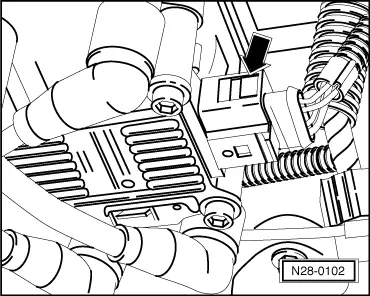
Checking ignition transformer

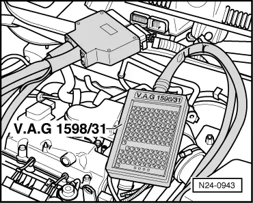
Special tools, workshop equipment, testers, measuring instruments and auxiliary items required

  • ◆ Test box V.A.G 1598/31
  • ◆ Hand multimeter V.A.G 1526 or multimeter V.A.G 1715
  • ◆ Adapter set V.A.G 1594
  • ◆ Diode test lamp V.A.G 1527
  • ◆ Current flow diagram

Check conditions

  • ● The battery voltage must be at least 11.5 V.
  • ● Hall sender must be OK, checking
    .
  • ● Engine speed sender must be OK, checking Page 24-68 .
 
N28-0102

Test sequence

  • ‒ → Pull 4 pin connector off ignition transformer -arrow-.

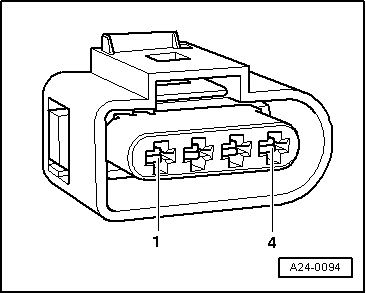
Checking voltage supply

Test conditions

 
N24-0831
  • ● → Fuse No. 34 must be OK.
 
N28-0133
  • ‒ → Using multimeter and adapter cables from V.A.G 1594 measure the supply voltage between contacts 2+4 of disconnected connector.
  • ‒ Switch on ignition.
         Specification: min. 11.5 V
  • ‒ Switch off ignition.

If no voltage is present:

 
A24-0094
  • ‒ → Check wire between 4 pin connector contact 2 and relay plate for open circuit according to current flow diagram.
         Wire resistance: max. 1.5 ω
  • ‒ Check wire between 4 pin connector contact 4 and earth for open circuit according to current flow diagram.
         Wire resistance: max. 1.5 ω

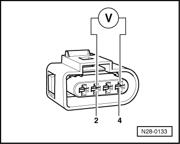
Checking activation

Warning!
During the following test do not touch the terminals of the ignition transformer or test cables.
 
N24-0739
  • ‒ → Remove cover above camshaft housing -arrows-.
 
N24-0736
  • ‒ → Pull plug -arrows- off all injectors.
 
A24-0094
  • ‒ → Connect diode test lamp V.A.G 1527 with adapter cables from V.A.G 1594 to
         contacts 1 + 4 (ignition output 1),
         contacts 3 + 4 (ignition output 2)
    of disconnected connector.
  • ‒ Operate starter and check the ignition signal from engine control unit.
         The LED must flicker
  • ‒ Switch off ignition.

If the LED flickers and there is voltage between contacts 2 + 4:

  • ‒ Replace ignition transformer (N152)
    , item 2 .

The LED does not flicker:
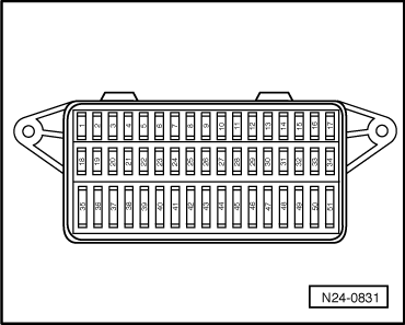
 
N24-0943
  • ‒ Check wiring => Page 28-16

Checking wiring

  • ‒ → Connect test box V.A.G 1598/31 to control unit wiring harness. The engine control unit remains disconnected.
 
A24-0094
  • ‒ → Check wiring for open circuit between test box and 4-pin connector using current flow diagram.
         Contact 1+socket 102
         Contact 3+socket 103
         Wire resistance: Max. 1.5 ω
  • ‒ Additionally check wires for short to one another.
         Specification: ∞ω

If no wiring fault is detected and voltage was present between contacts 2+4:

  • ‒ Replace engine control unit
    => Page 24-117 .

Checking secondary resistance

 
N28-0134
  • ‒ → Check the secondary winding on terminal 4 between
         Cyl. 1+Cyl. 4,
         Cyl. 2+Cyl. 3.
         Specification: 4.0... 6.0 kω (at 20 °C)

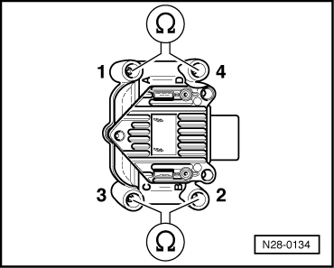
If the specifications are not attained:

  • ‒ Replace ignition transformer (N152)
    => Page 28-3 , item 2 .

Checking knock sensor > < Checking Hall sender