volkswagen Workshop Repair Guides

Volkswagen Workshop Service and Repair Manuals

Checking signal from brake light switch and brake pedal switch > < Checking speed signal
4LV injection and ignition system
Checking additional signals
Checking signal from/to air conditioning system

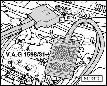
Special tools, workshop equipment, testers, measuring instruments and auxiliary items required

  • ◆ Fault reader V.A.G 1551 or vehicle system tester V.A.G 1552 with cable V.A.G 1551/3
  • ◆ Test box V.A.G 1598/31
  • ◆ Hand multimeter V.A.G 1526 or multimeter V.A.G 1715
  • ◆ Adapter set V.A.G 1594
  • ◆ Current flow diagram

Test conditions

  • ● Air conditioner functioning OK.
  • ● Air conditioner must be switched off
  • ● No faults must be stored in fault memory
    , interrogating fault memory
  • ● Vehicle at room temperature (warmer than + 15 °C).

Test sequence

  • ‒ Connect fault reader V.A.G 1551 (V.A.G 1552). Start engine and select "Address word" 01 of engine control unit. When doing this the engine must be running at idling speed.
    (Connecting fault reader and selecting engine control unit => Page 01-8 .)
 
→ Indicated on display:
Rapid data transfer     HELP
Select function XXX
  • ‒ Press keys 0 and 8 for the function "Read measured value block" and confirm entry with Q key.
 
→ Indicated on display:
Read measured value block     HELP
Input display group number XXX
  • ‒ Press keys 0, 5 and 0 for "Display group number 50" and confirm entry with Q key.
 
→ Indicated on display:
(1...4 = Display zones)
Read measured value block 50     ⇒
     1     2     3     4
  • ‒ Observe display in display zones 3 and 4. They must show
         OFF.
  • ‒ Switch on air conditioning system.
  • ‒ Select lowest temperature and highest blower speed.
  • The display in display zones 3 and 4 must change to
         ON.
  • ‒ Press the ⇒key.
  • ‒ Press keys 0 and 6 for the "End output" function and confirm input with the Q key.
  • ‒ Switch off ignition.

If the display does not change:

 
N24-0943
  • ‒ → Connect test box V.A.G 1598/31 to control unit wiring harness. The engine control unit remains disconnected.
  • ‒ Check wiring for open circuit between test box sockets 40 + 41 and air conditioner system using current flow diagram.
         Wire resistance: max. 1.5 ω

Checking signal from brake light switch and brake pedal switch > < Checking speed signal