-
‒ Apply brake and hold down brake pedal. The engine speed will be raised automatically. After a moment, the following appears in display zone 2:
B1-P2 OK
If "B1-P2 n.OK"
appears in display zone 2,
-
‒ Check Lambda probe 2 voltage at idling speed in display zone 1.
Specification: 0.000...1.000 V
-
‒ Continue check according to following table.
|
|
|---|
|
Display
|
Cause
|
Continuation of check
|
|
Between 0.400...
0.500 V
|
Open circuit
|
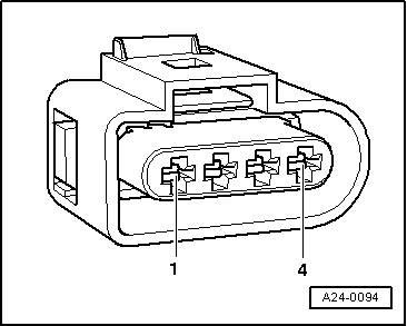
=> Page 24-105
checking Lambda probe wiring
|
|
1.105 V
|
Short to positive
|
|
|
0.000 V
|
Short to earth
|
|
If the Lambda regulation in display zone 1 does not fluctuate as stated:
-
‒ Press ⇒key.
-
‒ Press keys 0 and 6 for the "End data transfer" function and confirm input with the Q key.
-
‒ Carry out road test and burn Lambda probes clean and repeat check.
Observe the valid safety precautions when carrying out a road test => Page 24-29
.
If the the specifications in display zone 1 are not obtained even after a test drive, or the value does not fluctuate by at least 2 %:
|