volkswagen Workshop Repair Guides

Volkswagen Workshop Service and Repair Manuals

Dismantling and assembling intake manifold > < General notes on injection
4LV injection and ignition system
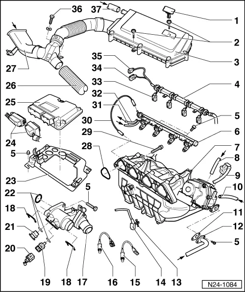
Servicing injection system
Removing and installing parts of the injection system
 
N24-1084
  • Plug
    • ◆ Note installation position
  • 3 Nm
    • ◆ Notes on installing
  • Air cleaner
    • ◆ Dismantling and assembling => Page 24-25
    • ◆ Removing and installing air cleaner
      => Page 24-28 , Fig. 3
  • Cable/line guide
    • ◆ Clipped onto fuel rail
  • 10 Nm
 
N24-1084
  • Fuel manifold with injectors
    • ◆ Dismantling and assembling => Page 24-22
  • Intake manifold
    • ◆ Dismantling and assembling => Page 24-19
  • From activated charcoal filter solenoid valve (N80)*/**

=> Repair group 20; Activated charcoal filter system

  • Connector
    • ◆ Black, 6-pin
    • ◆ For throttle valve control part (J338)
    • ◆ Connector contacts are gold-plated
  • From brake servo
 
N24-1084
  • Gasket
    • ◆ Renew
  • From exhaust gas recirculation valve

=> Repair group 26; Exhaust gas recirculation system; Servicing parts of the exhaust gas recirculation system

  • 5 Nm
  • Engine speed sender (G28)*
    • ◆ To remove, remove starter:

=> Electrical system; Repair group 27; Starter; Removing and installing starter

    • ◆ Checking => Page 24-68
    • ◆ Fitting location => Page 24-1 , fitting location overview
 
N24-1084
  • Lambda probe 2 after catalyst (G130)*, 50 Nm
    • ◆ Grease only the threads with "G 052 112 A3"; "G 052 112 A3" must not get into the slots on the probe body
    • ◆ Remove and install with ring spanner 3337
    • ◆ With 4-pole connector
    • ◆ Contacts 3 and 4 gold plated
    • ◆ Probe heating voltage supply via fuel pump relay (J17)
    • ◆ Checking Lambda probe and Lambda regulation after catalyst => Page 24-100
    • ◆ Checking Lambda probe heating for Lambda probe after catalyst => Page 24-38
    • ◆ Location: Behind catalyst
 
N24-1084
  • Lambda probe 1 before catalyst (G39)*, 50Nm
    • ◆ Grease only the threads with "G 052 112 A3"; "G 052 112 A3" must not get into the slots on the probe body
    • ◆ Remove and install with ring spanner 3337
    • ◆ With 6-pin connector
    • ◆ Contacts gold plated
    • ◆ Probe heating voltage supply via fuel pump relay (J17)
    • ◆ Checking Lambda probe and Lambda regulation before catalyst
      => Page 24-93
    • ◆ Checking Lambda probe heating before catalyst => Page 24-33
    • ◆ Checking Lambda probe ageing Lambda probe 1 => Page 24-106
    • ◆ Fitting location: In exhaust manifold
 
N24-1084
  • Thermostat housing
  • Retaining clip
    • ◆ Check seated securely
  • Coolant temperature sender (G62)*
    • ◆ For engine control unit
    • ◆ With coolant temperature gauge sender (G2)
    • ◆ If necessary release pressure in cooling system before removing
    • ◆ Resistance value between contacts C and D
      , Fig. 1
    • ◆ Checking
  • Connector
    • ◆ Black, 4-pin
    • ◆ For coolant temperature sender (G62) and coolant temperature gauge sender (G2)
    • ◆ Contacts gold plated
 
N24-1084
  • Plug
    • ◆ If necessary release pressure in cooling system before removing
  • O-ring
    • ◆ Renew if damaged
  • Retaining frame
  • Connector
    • ◆ Only disconnect or connect with ignition switched off
  • Engine control unit*
    • (4LV injection system control unit -J537)
    • ◆ Checking voltage supply => Page 24-112
    • ◆ Procedure after voltage supply open circuit => Page 24-115
    • ◆ Renew => Page 24-117
    • ◆ Coding => Page 24-120
    • ◆ Fitting location => Page 24-1 , engine compartment overview
 
N24-1084
  • Warm air intake hose
    • ◆ From warm air collector plate:

=> Repair group 26; Removing and installing parts of exhaust system

  • Connecting piece for cold air intake
    • ◆ Additionally secured on body with retaining clip
  • Seal
    • ◆ Renew
  • 20 Nm
  • Vacuum hose
 
N24-1084
  • Supply hose
    • ◆ Black with white marks
    • ◆ Secure with spring-type clips
    • ◆ Check securely seated
    • ◆ From fuel filter:

=> Repair Group 20; Removing and installing parts of fuel supply system; Removing and installing fuel tank with attachments and fuel filter

  • Return hose
    • ◆ Blue or with blue marking
    • ◆ Secure with spring-type clips
    • ◆ Check securely seated
    • ◆ To the fuel delivery unit in fuel tank

=> Repair Group 20; Removing and installing parts of fuel supply system; Removing and installing fuel tank with attachments and fuel filter

 
N24-1084
  • Connector
    • ◆ Black, 2-pin
    • ◆ For injector (N30...N33)
  • Connector
    • ◆ Black, 2-pin
    • ◆ For knock sensor 1 (G61)
    • ◆ Connector contacts are gold-plated
    • ◆ Fitting location => Page 24-1 , engine compartment overview
  • Connector
    • ◆ Black, 4-pin
    • ◆ For intake manifold pressure sender and sender for intake air temperature in intake manifold
    • ◆ Connector contacts are gold-plated
    • ◆ Fitting location => Page 24-1 , engine compartment overview
 
N24-1084
  • 5 Nm
  • Crankcase breather hose
    • ◆ From oil separator:

=> Repair group 17; Removing and installing parts of lubrication system

Dismantling and assembling intake manifold > < General notes on injection