volkswagen Workshop Repair Guides

Volkswagen Workshop Service and Repair Manuals

Checking intake manifold temperature sender G72 > < Checking engine speed sender G28
Checking coolant temperature senderG62
Checking coolant temperature sender -G62-
Special tools and workshop equipment required
t  Hand multimeter -V.A.G 1526C- or multimeter -V.A.G 1715-
t  Fault reader -V.A.G 1551- or vehicle system tester -V.A.G 1552- with diagnosis cable -V.A.G 1551/3-
t  Adapter set -V.A.G 1594C-
t  Adapter cable, 121-pin -V.A.G 1598/31-
t  Current flow diagram
Test prerequisite
l  Engine must be cold.
Test procedure
–  Connect fault reader -V.A.G 1551- or vehicle system tester -V.A.G 1552- and select engine electronics control unit with “address word” 01. Engine must be idling. (Connecting fault reader -V.A.G 1551- and selecting engine electronics control unit → Chapter).
   
Indicated on display:
–  Press keys 0 and 8 for function “Read measured value block” and confirm entry with Q key.
 
Rapid data transfer                 HELP
Select function XX                    
Indicated on display:
–  Press keys 0, 0 and 7 for “Display group number 7” and confirm entry with Q key.
 
Read measured value block                     
Input display group number XXX       
–  Indicated on display:
–  Check coolant temperature value in display zone 4. The temperature value must Increase uniformly and without interruption.
–  In case of faults the fuel temperature or - 4.5 °C is displayed as a substitute.
–  Press key.
–  Press keys 0 and 6 for function “End output” and confirm entry with Q key.
–  Switch off ignition.
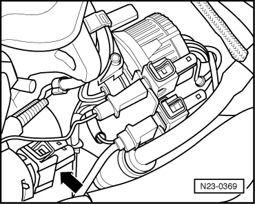
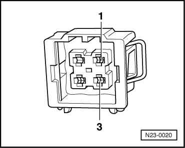
–  If no realistic display appears in display zone 4, or either the fuel temperature or -4.5°C is displayed as a substitute, check coolant temperature sender -G62- and line connections to sender as follows:
 
Read measured value block 7          ->
15.4°C            15.9°C       16.7°C
–  Pull 4-pin connector off coolant temperature sender -G62- with coolant temperature gauge sender -G2--arrow-.
  N23-0369
–  Perform resistance measurement on coolant temperature sender -G62- contact 1 (earth) and 3 (signal).
  N23-0023
Specification see diagram.
Scale A shows resistance values for temperature range 0...50 °C and scale B the values for temperature range 50...100 °C.
Examples:
t  30 °C corresponds to a resistance of 1500..2000 Ω
t  80 °C corresponds to a resistance of 275..375 Ω
If the specification is not achieved:
–  Renew the coolant temperature sender -G62-.
–  Read fault memory, if necessary, repair any faults and then clear fault memory → Chapter, Reading and clearing fault memory.
If the specification is attained:
  N24-0157
–  Connect adapter cable, 121-pin -V.A.G 1598/31- to control unit wiring harness. The engine control unit remains disconnected.
  N01-0369
–  Check wiring between 121-pin adapter cable -V.A.G 1598/31- and 4-pin connector for open circuit according to current flow diagram. Contact 1 + socket 104 Contact 3 + socket 112
Cable resistance: max. 1.5 Ω.
–  Also check wiring for short to one another, short to vehicle earth and short to battery positive.
Specification: ∞ Ω.
If no fault in lines is detected:
–  Renew engine control unit → Chapter.
  N23-0020

Checking intake manifold temperature sender G72 > < Checking engine speed sender G28