volkswagen Workshop Repair Guides

Volkswagen Workshop Service and Repair Manuals

Checking and adjusting idling switch > < Checking engine operating mode
Mono Motronic injection and ignition system
Mono-Motronic injection and ignition system
Checking throttle valve positioner

Checking function

Functional check , Final control diagnosis

Checking activation

Special tools, testers and auxiliary items

  • ◆ Hand multimeter V.A.G 1526 or multimeter V.A.G 1715
  • ◆ Diode test lamp V.A.G 1527
  • ◆ Test box V.A.G 1598/18
  • ◆ Adapter set V.A.G 1594
  • ◆ Current flow diagram

Test conditions

  • ● Fault reader V.A.G 1551 (V.A.G 1552) connected
  • ● Ignition switched off

Test sequence

  • ‒ Remove air cleaner.
 
N24-0140
  • ‒ → Pull plug -1- off throttle valve positioner (V60) -2- .
  • ‒ Connect diode test lamp V.A.G 1527 with aux. cables from V.A.G 1594 to contacts 1+6 of the connector.
  • ‒ Bridge contacts 4+5 with aux. cables from V.A.G 1594.
  • ‒ Switch on ignition and again perform self-diagnosis until the throttle valve positioner is activated.
         LED must light up.
  • ‒ Slowly open throttle valve slightly. The display must
         briefly change to the other LED
    and then
         go out.

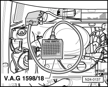
Note:

If the check has to be repeated separate aux. cables on contacts 4+5 and then reconnect.

  • ‒ Carry out final control diagnosis up to end.
  • ‒ Switch off ignition and connect plug.
  • ‒ Interrogate fault memory=> Page 01-6 .

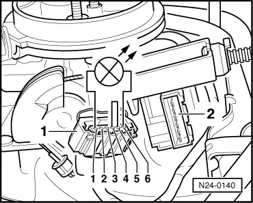
If the LEDs do not light up:
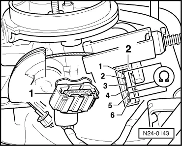
  • ‒ Switch off ignition
 
N24-0137
  • ‒ → Connect test box V.A.G 1598/18 to control unit wiring loom.
  • ‒ Check wiring between test box and 6 pin connector for open circuit according to current flow diagram.
         Contact 1+socket 26
         Contact 2+socket 16
         Contact 3+socket 23
         Contact 4+socket 20
         Contact 5+socket 10
         Contact 6+socket 2
         Wire resistance: Max. 1.5 ω
  • ‒ Check wiring at 6 pin connector for short to one another.
         Specification: ∞ω

Checking resistance

 
N24-0143

Test conditions

  • ● Ignition switched off.

Test sequence

  • ‒ Remove air cleaner.
  • ‒ → Pull connector -1- off throttle valve positioner -2-.
  • ‒ Check resistance with hand multimeter V.A.G 1526 and aux. cables from V.A.G 1594 at contacts of throttle valve positioner as follows:
         Specifications:
         between contacts 1+6 = 3...200 ω
         between contacts 4+5
         Throttle valve closed = max. 200 ω
         Throttle valve open =∞ ω

If the specifications between contacts 4+5 are not attained:

  • ‒ Check idling switch => Page 24-37 .

Checking and adjusting idling switch > < Checking engine operating mode