volkswagen Workshop Repair Guides

Volkswagen Workshop Service and Repair Manuals

Checking rpm signal > < Checking signal from/to air conditioning system
Motronic inj. and ignition system (2-valve, roller rocker finger)
Checking additional signals
Checking signal from brake light switch and brake pedal switch

Special tools, workshop equipment, testers, measuring instruments and auxiliary items required

  • ◆ Hand multimeter V.A.G 1526 or multimeter V.A.G 1715
  • ◆ Adapter set V.A.G 1594
  • ◆ Test box V.A.G 1598/22
  • ◆ Current flow diagram

Check conditions

 
N24-0831
  • ● → Fuses No. 15 and 24 must be OK.
  • ● The battery voltage must be at least 11.5 V.

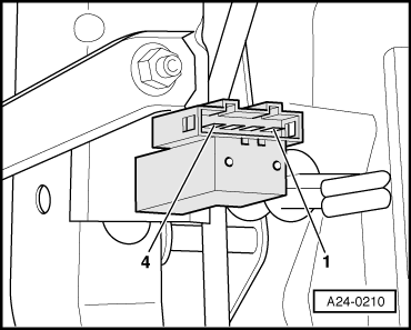
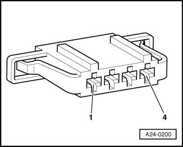
Test sequence

Note:

The brake pedal switch (F47) and brake light switch (F) are together in one housing.

  • ‒ Pull the connector off brake light/brake pedal switch.
 
A24-0210
  • ‒ → Connect the multimeter to measure resistance between contacts 1 and 4.
         Specification: ∞ ω (no continuity)
  • ‒ Depress brake pedal.
         Specification: approx. 0 ω
  • ‒ Connect the multimeter to measure resistance between contacts 2 and 3.
         Specification: approx. 0 ω
  • ‒ Depress the brake pedal.
         Specification: ∞ ω (no continuity)

If the specifications are not attained:

  • ‒ Replace the brake light/brake pedal switch.

If the specifications are obtained:

 
A24-0200
  • ‒ → Connect multimeter to measure voltage between contact 1 and earth.
         Specification: at least 11.5 V
  • ‒ Switch ignition on.
  • ‒ Connect the multimeter to measure voltage between contact 2 and earth.
         Specification: at least 11.5 V

If the specifications are not obtained:

  • ‒ Check the wire between 4-pin connector contact 1 and main fuse/contact 2 and central electrics using current flow diagram.

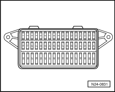
=> Current flow diagrams, Electrical fault finding and Fitting locations binder

 
N24-0709

If the specification is obtained:

  • ‒ Remove wiper arms and cowl panel:

=> Electrical system; Repair group 92; windscreen wiper system; removing and installing windscreen wiper system

  • ‒ → Connect test box V.A.G 1598/22 to control unit wiring harness.
 
A24-0200
  • ‒ → Check wiring for open circuit between test box and 4-pin connector using current flow diagram.
         Contact 3+socket 51
         Contact 4+socket 23
         Wire resistance: Max. 1.5 ω
  • ‒ Additionally check wires for short to one another.
  • ‒ Additionally check the wiring for short to battery positive or earth.

Checking rpm signal > < Checking signal from/to air conditioning system