
Polo Mk3
 |
|
Check conditions
Test sequence
|
| → Indicated on display: |
|
||
|
| → Indicated on display: |
|
||
|
|
→
Indicated on display: (1...4 = Display zones) |
|
||
Note: The Lambda probe heating may be switched on or off depending on the operating mode of the engine, therefore the display in display zone 2 may show "Htg.bC.ON or alternating from Htg.bC.ON to Htg.bC.OFF. If the specification is obtained:
If the specification is not obtained: |
 |
|
|
Only engines which conform to EU 4 standard (engine code AKP, AUC, AUD) Engines conforming to MVEG II standard (engine code AKK, ALD) => Page 24-39 .
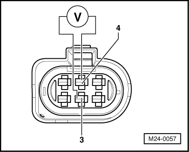
Checking voltage supply |
 |
|
If no voltage is present: |
 |
|
|
 |
|
If the specification is obtained:
|
|
|
|
Only engines conforming to MVEG II standard (engine codes AKK, ALD)
|
 |
|
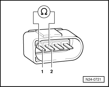
Note: The heater element resistance is approx. 1...5 ω at room temperature. Even slight increases in room temperature increase the resistance greatly. If it is determined that probe heating has an open circuit:
If probe heating has continuity: |
 |
|
|
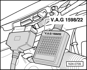
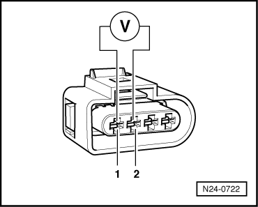
Checking voltage supply
If no voltage is present: |
 |
|
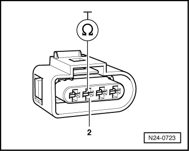
If the specification is obtained:
|