
Polo Mk3
|
Servicing injection system
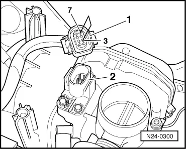
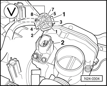
Checking throttle valve control part
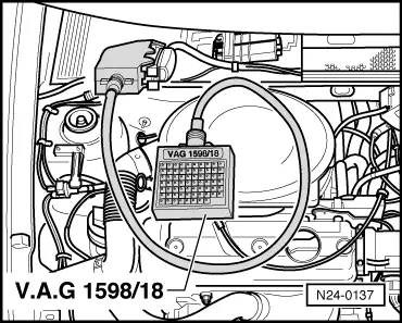
Note: If the throttle valve control part (J338) is removed and installed or replaced the basic setting must be performed . Special tools, testers, measuring instruments and auxiliary items required
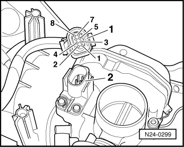
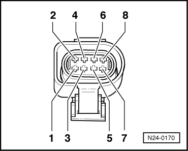
Checking idling switch
|
| → Indicated on display: |
|
||
|
| → Indicated on display: |
|
||
|
|
→
Indicated on display: (1...4 = Display zones) |
|
|||||||||
If the specifications are not obtained:
Continuation of check when display is always at 1 |
 |
|
Display 0:
Display 1:
If the voltage supply and wiring is OK: |
 |
|
|
Continuation of check when display constantly shows 0
Display 1:
Display 0:
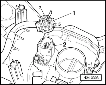
If the voltage supply and wiring is OK: Checking throttle valve positioner and throttle valve positioner potentiometer Test conditions
Test sequence
|
| → Indicated on display: |
|
||
|
| → Indicated on display: |
|
||
|
| →
Indicated on display: (1...4 = Display zones) |
|
||
If the specification is not obtained: |
 |
|
If no fault is detected:
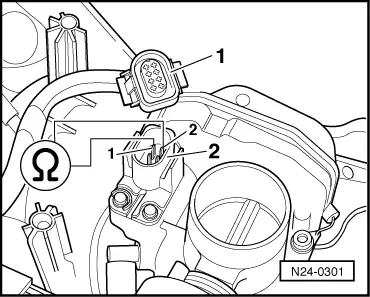
Checking throttle valve potentiometer Test conditions
Test sequence
|
| → Indicated on display: |
|
||
|
| → Indicated on display: |
|
||
|
| →
Indicated on display: (1...4 = Display zones) |
|
|||||||||
If the figure does not increase uniformly:
If the display constantly shows 0 <° or is above 90 <°:
Continuation of check when display 0 <°: |
 |
|
Display above 90 <°:
Display 0 <°:
If the voltage supply and wiring is OK: Continuation of check when display is above 90 <°: |
|
|
Display 0 <°:
Display above 90 <°:
If the voltage supply and wiring is OK: Checking voltage supply and wiring to control unit |
 |
|
|
 |
|
|
 |
|
If no wiring fault is detected:
|