
Polo Mk3
 |
|
Notes:
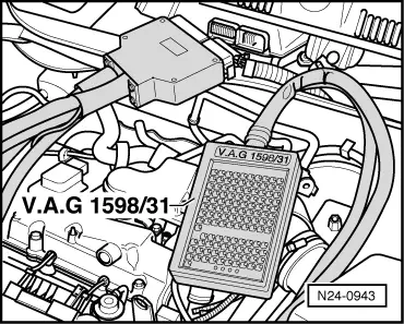
Work sequence
|
| → Indicated on display: |
|
||
|
| → Indicated on display: |
|
||
|
Activating fuel pump relay (J17):
|
| → Indicated on display: |
|
||
Note: During the activation of the fuel pump relay the fuel pump must be heard to run at intervals. If the relay does not click:
=> Current flow diagrams, Electrical fault finding and Fitting locations Activating activated charcoal filter solenoid valve 1 (N80):
|
| → Indicated on display: |
|
||
If the solenoid valve does not click: |
 |
|
|
 |
|
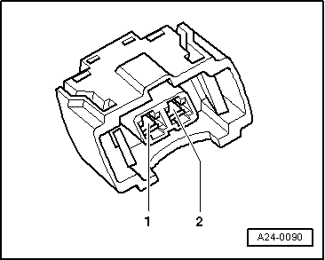
LED flashes:
|
 |
|
LED does not flash:
|
 |
|
If no fault is detected in the wiring:
Activating secondary air inlet valve (N112):
|
| → Indicated on display: |
|
||
Activating secondary air pump relay (J299):
|
| → Indicated on display: |
|
||
|
| → Indicated on display: |
|
||
|
| → Indicated on display: |
|
||
|