volkswagen Workshop Repair Guides

Volkswagen Workshop Service and Repair Manuals

Faults displayed by warning lamps K47 and K118 > < Fault finding with fault reader V.A.G 1551 or tester VAS 5051 on ABS, ITT Mark 04 GI (flow chart)
Running gear self-diagnosis for ABS
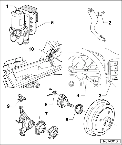
Electrical/electronic components and fitting locations
 
N01-0010
  • ABS hydraulic unit -N55
    • ◆ Located on left of engine compartment.
    • ◆ The hydraulic pump -V64- and the inlet/outlet valves in the hydraulic unit are checked by self-diagnosis
    • ◆ The hydraulic pump -V64- and valve block must not be separated from one another
    • ◆ Removing and installing

=> Brake systems; Repair group 45

    • ◆ When changing the hydraulic unit, always seal the old part with the plugs from the repair set Part No.
      1H0 698 311 A
 
N01-0010
  • Brake light switch -F
    • ◆ The brake light switch is open in the rest position;
    • ◆ Can be checked via reading measured value block
    • ◆ Adjusting

=> Brake system; Repair group 46; Brake pedal - Assembly overview; Adjusting brake light switch

  • ABS warning lamp -K47
    • Locations:
    • ◆ LHD, on right of dash panel insert
    • ◆ RHD, on left of dash panel insert
    • Function:
  • Brake system warning lamp -K118
    • ◆ Location: In the dash panel insert
    • Function:
 
N01-0010
  • ABS control unit -J104
    • ◆ Location: on hydraulic unit on left of engine compartment
    • ◆ Checking multi-pin connector to control unit
    • ◆ Do not disconnect connector before successfully completing self-diagnosis. Switch ignition off before separating connection.
  • Rotor for speed sensor
    • ◆ Rotor and speed senders for rear left and right-hand sides are identical
    • ◆ Removing and installing

=> Running gear, axles, steering; Repair group Gr. 42; Servicing wheel bearings

 
N01-0010
  • Rotor for speed sensor
    • ◆ Rotor and speed senders for front left and right-hand sides are identical
    • ◆ Removing and installing

=> Running gear, Axles, Steering; Repair group 40; Servicing front suspension

  • Rear right/left speed sensor -G44-/-G46
    • ◆ Before inserting the sensor clean the inner surface of the sensor mounting and coat with lubricating paste
      G 000 650
    • ◆ When connecting the speed sensor wire ensure it is not twisted in the wheel housing
    • ◆ Securing bolt tightening torque
      - 10 Nm
 
N01-0010
  • Front right/left speed sensor -G45-/-G47
    • ◆ Before inserting the sensor clean the inner surface of the sensor mounting and coat with lubricating paste
      G 000 650
    • ◆ When connecting the speed sensor wire ensure it is not twisted in the wheel housing
    • ◆ Securing bolt tightening torque
      - 10 Nm
  • Diagnostic connections
    • ◆ Location: Behind driver's side stowage compartment

Faults displayed by warning lamps K47 and K118 > < Fault finding with fault reader V.A.G 1551 or tester VAS 5051 on ABS, ITT Mark 04 GI (flow chart)