volkswagen Workshop Repair Guides

Volkswagen Workshop Service and Repair Manuals

Test table > < Test prerequisites
Running gear self-diagnosis for ABS
Electrical check of ABS, ABS/EDL ITT Mark 20 GI and ITT Mark 20 IE
Multi-pin connector with contact assignment
 
N29-0001

All contacts not listed are currently not assigned and must never be connected to other components!

→ Contact assignment of connectors for voltage supply and self-diagnosis with the fault reader V.A.G 1551

Contact 4

=

Earth (terminal 31)

Contact 16

=

Positive (terminal 30)

Contact 7

=

K wire to contact 7 of multi-pin connector T25 of control unit -J104

 
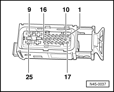
N45-0037

→ Contact assignment of connector T25 wiring loom/control unit - J104

Contact

Wiring connection to component ...

1

=>

Front left speed sensor -G47

2

=>

Front left speed sensor -G47

3

=>

Vacant

4

=>

Voltage supply terminal X

5

=>

Rear left speed sensor -G46

6

=>

Rear left speed sensor -G46

7

=>

Connector T16/7, K wire

8

=>

Earth connection in engine compartment wiring harness

9

=>

Voltage supply from battery +

10

=>

Vacant

11

=>

Vacant

12

=>

Vacant

Contact

Wiring connection to component ...

13

=>

Vacant

14

=>

Coding bridge to contact 21

15

=>

Vacant

16

=>

ABS warning lamp activation

17

=>

Vacant

18

=>

Brake light switch -F-

19

=>

Front right speed sensor -G45

20

=>

Front right speed sensor -G45

21

=>

Coding bridge to contact 14

22

=>

Rear right speed sensor -G44

23

=>

Rear right speed sensor -G44

24

=>

Earth point left in engine compartment and earth connection in engine compartment wiring harness

25

=>

Voltage supply from battery +

Test step overview

Component to be tested

Voltage supply for hydraulic pump -V64- to control unit -J104

- Perform test step 1

Voltage supply for valves in hydraulic unit -N55- to control unit -J104

- Perform test step 2

Voltage supply (terminal X) to control unit -J104

- Perform test step 3

Function of brake light switch -F

- Perform test step 4

Resistance of front right speed sensor -G45

- Perform test step 5

Resistance of front left speed sensor -G47

- Perform test step 6

Resistance of rear right speed sensor -G44

- Perform test step 7

Resistance of rear left speed sensor -G46

- Perform test step 8

Voltage signal of front right speed sensor -G45

- Perform test step 9

Voltage signal of front left speed sensor -G47

- Perform test step 10

Component to be tested

Voltage signal of rear right speed sensor -G44

- Perform test step 11

Voltage signal of rear left speed sensor -G46

- Perform test step 12

Coding bridge

- Perform test step 13

Voltage supply for V.A.G 1551, connector T16

- Perform test step 14

Resistance of K wire for self-diagnosis, connector T16

- Perform test step 15

Function of ABS warning lamp -K47

- Perform test step 16

Function of brake system warning lamp -K118

- Perform test step 17

Function of hydraulic pump -V64

- Perform test step 18

Test table > < Test prerequisites