
Polo Mk4
| Central locking (sedan) - assembly overview |
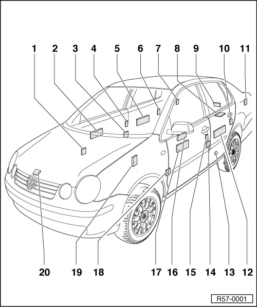
| 1 - | Electric connection |
| q | Installation location: Pillar A |
| q | to disconnect the connection, disengage the bellows in the pillar |
| 2 - | Right front door locking command |
| q | Integrated to the electric window mechanism motor |
| q | Remove: |
| q | Remove the door lining → General body repairs, interior; Rep. Gr.70 |
| q | Remove the subframe → Chapter. |
| q | Remove the fastening screws from the electric window mechanism motor. |
| 3 - | Electric connection |
| q | Installation location: Pillar B |
| q | to disconnect the connection, disengage the bellows in the pillar |
| 4 - | Right front door lock |
| q | The door lock is fastened to the subframe. |
| q | The electric locking mechanism motor is integrated to the door lock. |
| q | Remove: |
| q | Remove the door lining → General body repairs, interior; Rep. Gr.70 |
| q | Remove the door latch → Chapter. |
| 5 - | Right rear door locking command |
| q | Integrated to the electric window mechanism motor |
| q | Remove: |
| q | Remove the door lining → General body repairs, interior; Rep. Gr.70 |
| q | Remove the subframe from behind. |
| q | Remove the fastening screws from the electric window mechanism motor. |
| 6 - | Right rear passenger door lock |
| q | The door lock is fastened to the subframe. |
| q | The electric locking mechanism motor is integrated to the door lock. |
| q | Remove: |
| q | Remove the door lining → General body repairs, interior; Rep. Gr.70 |
| q | Remove the door latch → Chapter. |
| 7 - | Motor to unlock the fuel reservoir lid V155 |
| q | Installation location: beneath the pillar C covering |
| q | To remove, before releasing the boot lining up to the wheel case → Body - Internal assembly works; Rep. Gr.70 |
| 8 - | Lid lock |
| q | Fastened to the lid |
| q | Remove and install → Chapter |
| 9 - | Lid device motor |
| q | Fastened to a support inside the lid |
| q | Remove and install → Chapter |
| 10 - | Left rear passenger door lock |
| q | The door lock is fastened to the subframe. |
| q | The electric locking mechanism motor is integrated to the door lock. |
| q | Remove: |
| q | Remove the door lining → General body repairs, interior; Rep. Gr.70 |
| q | Remove the door latch → Chapter. |
| 11 - | Electric connection |
| q | Installation location: in the left side panel area, covered by the side lining of the luggage compartment |
| q | Remove the lining from the luggage compartment → Body - Internal assembly works; Rep. Gr.70. |
| 12 - | Left rear passenger door command unit |
| q | Integrated to the electric window mechanism motor |
| q | Remove: |
| q | Remove the door lining → General body repairs, interior; Rep. Gr.70 |
| q | Remove the subframe from behind. |
| q | Remove the fastening screws from the electric window mechanism motor. |
| 13 - | Horn and two-sound horn -H1- |
| q | Installation location: on the left area in front of the rear axle on the lower floor |
| 14 - | Connection point |
| q | Installation location: Pillar B |
| q | to disconnect the connection, disengage the bellows in the pillar |
| 15 - | Left front door lock |
| q | The door lock is fastened to the subframe. |
| q | The electric locking mechanism motor is integrated to the door lock. |
| q | Remove: |
| q | Remove the door lining → General body repairs, interior; Rep. Gr.70 |
| q | Remove the door lock → Chapter. |
| 16 - | Control unit |
| q | Installed on the door lining |
| q | Remove: |
| q | Remove the door lining → General body repairs, interior; Rep. Gr.70 |
| 17 - | Left front door locking command |
| q | Integrated to the electric window mechanism motor |
| q | Remove: |
| q | Remove the door lining → General body repairs, interior; Rep. Gr.70 |
| q | Remove the subframe. |
| q | Remove the fastening screws from the electric window mechanism motor. |
| 18 - | Electric connection |
| q | Installation location: Pillar A |
| q | to disconnect the connection, disengage the bellows in the pillar |
| 19 - | Central command for “Convenience” system |
| q | assembled to a support in the middle instrument panel support |
| q | Installation location: beneath the instrument panel (above the accelerator pedal, in case of steering wheel on the left, and above the clutch pedal, in case of steering wheel on the right) |
| q | Remove and install → Chapter |
| 20 - | Bonnet latch |
| q | The Contact switch for engine compartment bonnet -F266- |
| q | Installation location: on the right panel. |
| q | Remove the rear door latch → Chapter. |