volkswagen Workshop Repair Guides

Volkswagen Workshop Service and Repair Manuals

ABS system components on the front and rear axles - remove and install > < Connect the brake pipes and the brake cylinder pipes to the hydraulic unit
Command unit for hydraulic unit - remove and install
Special tools and workshop equipment required
   
t  "Torque wrench - 5 to 50 Nm (enc. 1/2")" -VAG 1331-
  W00-0427
t  Brake pedal pressing device -VAG 1869/2-
  W00-0679
Plug repair set 1H0 698 311 A
After disconnecting the command device from the hydraulic unit, always place the valve tube transport protection in the hydraulic unit.
Hydraulic units without the transport protection are not covered by warranty.
1 - Valve tube transport protection
2 - Plugs M 10
3 - Plugs M 12
Remove
Installation location:
The command unit is screwed to the hydraulic system unit and is found in the right side of the engine compartment.
  WARNING
The brake pipes in the hydraulic unit area must not be bent.
–  Note the coding in vehicles with code radio equipment, request such coding if necessary.
–  Disconnect the battery → Electrical system; Rep. Gr.27.
3 cylinders, injection engine:
–  Disconnect the vacuum hoses from the upper air filter case section.
  N45-0039
–  Remove the cover by the points marked with -arrows-.
4 cylinders, injection engine:
–  Pull the hose from the oil separator and the check valve on the upper air filter case section.
  N24-1488
–  Remove the cover by the points marked with -arrows-.
3-cylinder diesel engine:
–  Pull the engine cover up and away from the fittings.
  R24-0029
–  Remove the intake hose -1-.
4-cylinder diesel engine with injector pump unit:
–  Pull the engine cover up and away from the fittings.
  N45-0324
–  Remove hose -1- and intake tube -2- → Engine; Rep. Gr.23.
or:
  N45-10060
–  Remove the flexible aspiration tube-1- and Motor for intake manifold valve -V157--2- → Engine; Rep. Gr.23.
4 cylinders, diesel engine with distribution injector pump:
–  Pull the engine cover up and away from the fittings.
  N45-10061
–  Remove the escape gas return valve -1-.
Continued for all vehicles;
  N45-0331
–  Push the connector safety lock -arrow- downwards.
  N45-10062
–  Release the connector from the command device -arrow- and remove by pulling it forward.
–  Place the Brake pedal pressing device -VAG 1869/2-.
–  Press the brake pedal with the actuator.
–  Place the bleeding hose of the bleeding reservoir over the left front brake caliper plug and open the plug.
–  Close the left front venting plug.
–  Put an adequate number of lint-free cloths under the command unit and the hydraulic unit.
Make sure that no brake fluid reaches the contacts.
  N45-10063
–  Loosen and hang the hydraulic unit brake pipes -3- to the brake cylinder.
–  Close the brake pipes and threaded holes with plugs from the repair set number 1H0 698 311 A.
–  Release the remaining hydraulic unit brake pipes.
  N45-10066
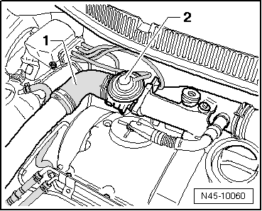
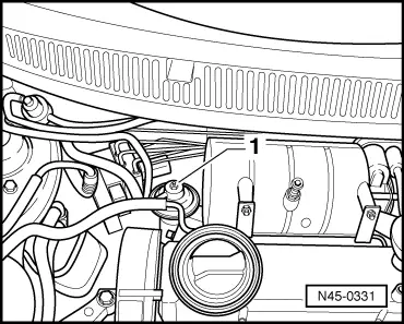
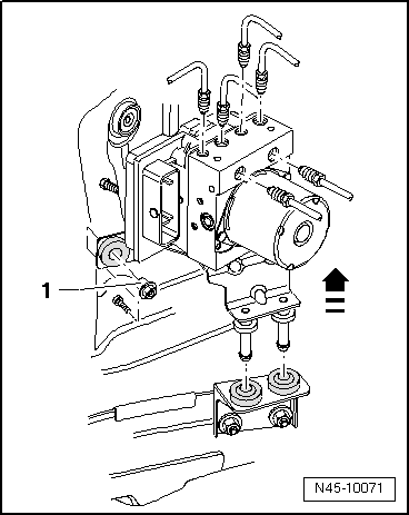
–  Unscrew the hexagonal nuts -1- from the command device/ hydraulic unit support.
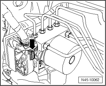
–  Remove the hydraulic unit along with the command unit, pulling it upward.
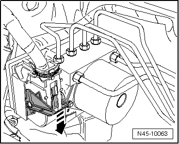
–  Remove the command device / hydraulic unit support.
Install
t  
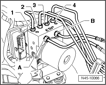
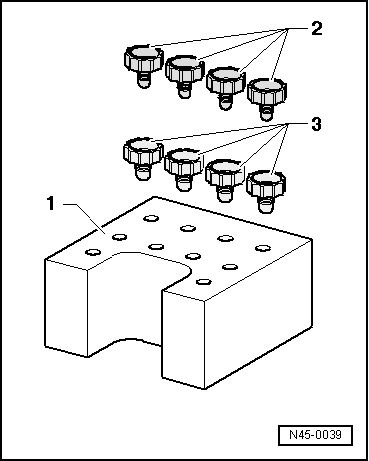
Only remove the plugs from the new hydraulic unit when the respective brake pipe is assembled.
t  If the plugs were already removed from the hydraulic unit, the brake fluid may leak to the point that proper venting and filling can no longer be ensured.
–  Install the ABS unit on the support.
–  The rest of the installation is processed in the reverse order from removal.
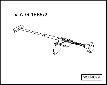
–  Remove the Brake pedal pressing device -VAG 1869/2-.
–  Bleed the brake system → Chapter.
–  Code ABS control unit -J104-.
Connect the Diagnosis, Measurement and Information System -VAS 5051A /52-and select the function → Chapter.
–  Code the radio.
  N45-10071
Tightening torques: 
Brake pipes in the ABS set: 
Threads M 10 x 114 Nm
Threads M 12 x 114 Nm
Hexagonal nut on the body20 Nm
Hexagonal head screw to hydraulic unit on the support8 Nm


ABS system components on the front and rear axles - remove and install > < Connect the brake pipes and the brake cylinder pipes to the hydraulic unit