volkswagen Workshop Repair Guides

Volkswagen Workshop Service and Repair Manuals

Hydraulic taps - check > < Valve command shaft - remove and install|Removal
Installation
Installation
  Note
t  During valve command shaft installation, cylinder 1 cams must face upwards.
   
t  When installing bearing caps mind hole eccentricity, before installing, place bearing cap and check installation position.
–  Lubricate command shaft contact surfaces.
–  Place command shaft on head.
–  Tighten bearings 2 and 4 caps alternately in cross and at 20 Nm.
–  Slightly lubricate bearing 1 and 5 cap supporting surface with seal AMV 174 004 01.
–  Install bearings 5, 1 and 3 covers at 20 Nm.
–  Place head cover 5 hammering gently command shaft
  Note
Remove sealing excess from head cover 1 and 5. Head/head cover sealing surface must be free of seals.
  V15-0098
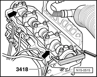
–  Lock command shaft as shown with command shaft rule 3418.
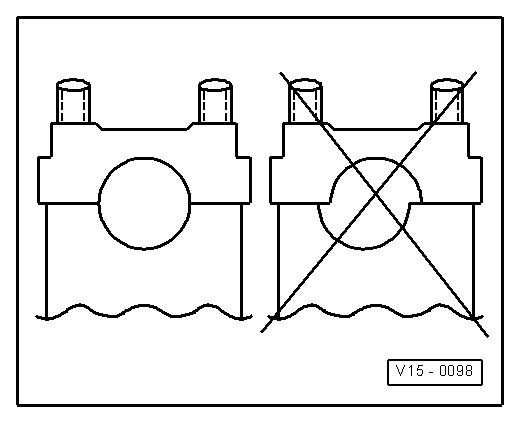
–  Calculate adjusting rule average as follows: Turn locked command shaft so that rule end touches head. On the other adjusting rule end measure space with a gauge. Place gauge with half of space measure between adjusting rule and head. Turn command shaft until adjusting rule touches gauge. Insert another gauge with same measure in the other end between rule and head.
  Note
Command shaft may also be locked with command shaft rule -T10098-.
When indented belt is installed and distribution timings are adjusted → Chapter, remove, install and adjust indented belt.
–  Remove mechanical distribution upper cover, head cover and vacuum pump.
  Note
After installing new hydraulic taps, engine may not be turned on for about 30 minutes. Hydraulic compensation elements must seat (otherwise, valves hit pistons).
  N15-0515

Hydraulic taps - check > < Valve command shaft - remove and install|Removal